Filter posts by category

Technology Guide

sheet metal fabrication services

Custom Sheet Metal Fabrication: 5052-H32 vs. 6061-T6

Aluminum has become the material of choice for Custom Sheet Metal Fabrication in aerospace, automotive manufacturing, electronic equipment, medical devices, and other fields by virtue of its lightweight and easy-to-process characteristics. Among them, 5052-H32 and 6061-T6 are the two most widely used aluminum materials, but there are big differences in their compositions and properties, which present different advantages and limitations in the actual fabricated sheet metal. The choice of aluminum material has a direct impact on the quality, cost and service life of the product, so it is important to choose the right aluminum alloy. The following article will outline the key differences between 6061 and 5052 and analyze their common challenges and solutions in Custom Sheet Metal Fabrication. 5052-H32 and the main difference between 6061-T6 Forming: 5052 h32 aluminum advantage is obvious, suitable for complex bending, deep stamping and other needs of large deformation process; 6061 t6 aluminum forming difficulty is higher, need to preheat or anneal to reduce […]

Custom Sheet Metal Fabrication: 5052-H32 vs. 6061-T6 Read More »

custom aluminum extrusion parts

How to do custom fabricated aluminum ——anodizing

In modern manufacturing, aluminum has become the material of choice in aerospace, industrial manufacturing, medical industry, automotive and many other fields by virtue of its light weight, good machinability and excellent heat dissipation performance. In custom fabricated aluminum, anodizing is a very important key link in the process. It can not only significantly improve the surface hardness and corrosion resistance of aluminum, but also provide products with rich colors and unique appearance. In the following, the article will introduce the detailed information of anodizing in custom fabricated aluminum process, mainly including the core definition, advantages, limitations, common types of anodizing, and list the related industry applications. what is custom fabricated aluminum–anodizing The anodic oxidation process in custom fabricated aluminum is a surface treatment of aluminum parts with the aim of optimizing the surface properties and appearance of the aluminum. At its core is an electrochemical process: Pretreatment: The custom fabricated aluminum parts are thoroughly cleaned and degreased to remove oils

How to do custom fabricated aluminum ——anodizing Read More »
aluminum sheet metal bending services

The Ultimate Guide On Sheet Metal Bending

In the field of metal processing and manufacturing, sheet metal bending is a very important process, which can accurately transform the shape of the sheet, from flat sheet to three-dimensional structure of the transformation. sheet metal bending process level will directly affect the accuracy, strength and appearance of the product quality, and it is widely used in aerospace, automotive manufacturing, It is widely used in aerospace, automotive, home appliance, construction and many other industries, so it is very important to have a comprehensive understanding of sheet metal bending! The article will analyze the knowledge of sheet metal bending in detail, first from its basic definition, then introduce the common types of technology, and finally list its main advantages and common applications to help you quickly and comprehensively understand sheet metal bending! What is sheet metal bending? Sheet metal bending is a cold working process in which a sheet metal is plastically deformed at a specific location by applying an external

The Ultimate Guide On Sheet Metal Bending Read More »
Duplex Stainless Steel Welding

Analysis and Applications of Duplex Stainless Steel Welding

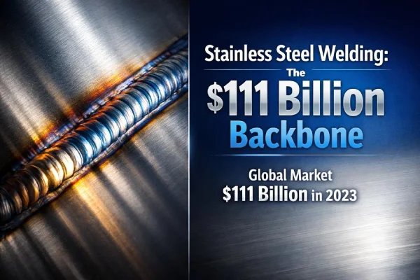
Stainless steel welding in offshore rigs, desalination plants, and chemical lines demands exact metallurgical control. Duplex grades (like 2205) and super duplex grades (like 2507) require a strict 50/50 austenite-ferrite balance to maintain structural integrity under pressure. Grand View Research reports the global stainless steel market topped $111 billion in 2023, driven heavily by energy infrastructure requiring materials that meet NACE MR0175 standards for sour service environments. Precision welding dictates whether these high-value joints survive or succumb to stress corrosion cracking. Types of Duplex Stainless Steel Welding Processes Duplex grades demand rigorous thermal control. The precise balance of strength and corrosion resistance depends on heat input (optimally 0.5 – 1.5 kJ/mm), specialized fillers, and reactive shielding choices. Gas Metal Arc Welding (GMAW) for Duplex Grades When running GMAW on Duplex Stainless Steel, thermal management sits at the center: Welding Parameters Current and voltage keep Heat Input strictly between 0.5 and 1.5 kJ/mm to prevent sigma phase precipitation. Travel speed protects

Analysis and Applications of Duplex Stainless Steel Welding Read More »

stainless steel deep drawing parts

Stainless Steel Stamping vs. Casting: Which Is Right for You?

In the field of precision metal forming, stainless steel stamping and casting represent two fundamentally different process logics. Casting begins with the filling of a mold with molten metal, while stamping achieves geometric shaping through the controlled deformation of solid material—a difference that directly determines the upper limits of a part’s mechanical properties, dimensional stability, and surface integrity. When it comes to 304 or 316 stainless steel stamping, the choice of process requires even greater care. As an experienced metal fabrication manufacturer, Supro’s engineering expertise indicates that when production volumes reach medium to high batches, tolerances are stringent, and the material must retain its original corrosion resistance, stainless steel metal stamping outperforms casting in both cost structure and quality consistency. This article will provide procurement and engineering teams with quantifiable decision-making criteria from three perspectives—process principles, technical constraints, and application suitability—to help you accurately identify the value boundaries of stainless steel stamping services in your projects. Understanding Stainless Steel Stamping

Stainless Steel Stamping vs. Casting: Which Is Right for You? Read More »

Progressive Die Metal Stamping

7 Key Advantages of Progressive Die Metal Stamping

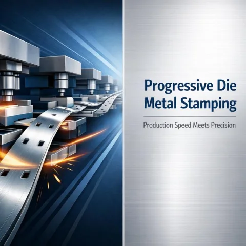
Progressive Die Metal Stamping is the critical differentiator between humming production lines and costly bottlenecks. In high-volume manufacturing, misfeeds and warped brackets erode margins. This process shapes metal in one continuous, automated sequence, eliminating clunky stop-and-go steps. When deadlines loom, you need components produced rapidly, dead-accurate, and highly budget-friendly. Why Choose Progressive Die For Volume Runs? For high-volume metal parts, Progressive Die Metal Stamping guarantees steady flow, tight tolerances, and strict material control. By seamlessly integrating the progressive feed, die architecture, and stamping mechanics, manufacturers achieve highly efficient, cost-smart production. Maximizing Throughput with Continuous Feed Lines High-volume output in Progressive Die Metal Stamping relies on optimal material flow, often exceeding 1,000 strokes per minute (SPM) for smaller components. Feed System Efficiency Continuous coil loading supports uninterrupted continuous feed Servo-driven rolls improve automation and indexing accuracy to within 0.0005 inches Stable indexing boosts overall throughput Press Line Configuration High-tonnage presses sustain rapid cycling Multi-station tooling enables parallel forming Integrated scrap removal

7 Key Advantages of Progressive Die Metal Stamping Read More »

stainless steel precision stamping

Stainless Steel Stamping: Definition and Applications

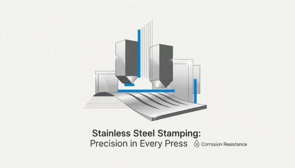
Stainless steel stamping is a precision manufacturing process that transforms materials such as 304 and 316L into high-strength, corrosion-resistant components through controlled deformation. Unlike conventional machining, this process requires strict attention to work hardening rates, die clearances, and dimensional stability during mass production. Key parameters such as grain structure consistency and thickness tolerances (typically controlled within ±0.05 mm) directly impact the performance of custom stainless steel stampings in applications such as automotive safety systems and medical device housings. When evaluating stainless steel stamping services, the key lies in process validation—particularly the ability to maintain statistical process control (SPC) during progressive die stamping. When producing custom stainless steel stampings, material certification compliant with the ASTM A240 standard and real-time optical measurement verification are essential prerequisites for ensuring the repeatability of critical components. This article provides a detailed analysis of stainless steel metal stamping and its common application areas to help you select the appropriate manufacturing processes and materials for your next

Stainless Steel Stamping: Definition and Applications Read More »

acrylic CNC machining parts

Acrylic CNC Machining: Process Parameter Optimization

In the field of acrylic CNC machining, the selection of process parameters directly determines success or failure in mass production. When orders transition from single-piece prototyping to large-scale production, the balance between spindle speed, feed rate, and cutting load is no longer merely a theoretical value—it becomes the bottom line for cost and yield. As a professional acrylic CNC machining manufacturer, we have found that many issues—such as edge whitening or dimensional drift—that appear to be caused by equipment actually stem from a failure to dynamically adjust parameters in response to material batches or tool wear. Differences in thermal response between cast and extruded acrylic, the stability of vacuum clamping, and even path redundancy in G-code are all amplified exponentially during large-scale acrylic PMMA CNC machining. This article will focus on the parameter logic for CNC machining acrylic in mass production scenarios—from equipment selection and toolpath optimization to post-processing integration—providing procurement and engineering teams with traceable, replicable delivery standards for

Acrylic CNC Machining: Process Parameter Optimization Read More »

high-quality acrylic CNC machining parts

Acrylic CNC Machining: Achieving Perfect Cutting Results

In the field of acrylic CNC machining, thermal management and cutting force control are critical to success. During the machining process, even the slightest misstep can result in white edges or fine cracks—which are unacceptable in acrylic CNC-machined parts such as medical device housings or high-end display stands. As a professional acrylic CNC machining manufacturer, Supro understands that the glass transition temperature of acrylic (PMMA) is only approximately 105°C, which is significantly lower than that of metal materials. To achieve a perfect cut, the chip load must be strictly controlled within the range of 0.1–0.2 mm/tooth, and single-flute O-groove cutters should be prioritized to optimize chip evacuation. Otherwise, frictional heat will rapidly cause the material to melt or crack due to stress. Therefore, providing high-quality acrylic CNC machining services requires not only advanced equipment but also precise parameter settings. This guide will focus on spindle speed, feed rate matching, and toolpath optimization to explain how to achieve crystal-clear, optical-grade surfaces

Acrylic CNC Machining: Achieving Perfect Cutting Results Read More »

acrylic cnc machining service

Acrylic CNC Machining: Applications and Precautions

Acrylic CNC machining is far from a simple cutting process; its core challenge lies in managing the material’s thermal sensitivity. If the heat generated by high-speed cutting is not precisely controlled through optimized spindle speeds, feed rates, and specialized coolant, it can easily lead to micro-cracks and edge misting, thereby compromising the optical properties of the finished parts. As your trusted acrylic CNC machining manufacturer, our process begins with a comprehensive DFM analysis using CAD/CAM simulation software to ensure toolpaths minimize cutting stresses. On vertical or horizontal machining centers, we utilize custom fixtures paired with geometrically optimized tools to achieve thermally stable cutting from roughing through finishing. Finally, verification via CMM and surface roughness meters ensures that every batch of acrylic CNC machining parts meets the strict standards required for everything from transparent prototypes to mass production. Whether you are seeking acrylic PMMA CNC machining solutions for automotive lighting or require highly transparent medical device housings, this article will provide

Acrylic CNC Machining: Applications and Precautions Read More »

mig welding

How to Perform MIG Welding on Aluminum

In aluminum fabrication, MIG welding is a key process for achieving both structural strength and aesthetic appeal. The core challenges of aluminum welding lie in its unique physical properties: the melting point of the surface oxide layer (approximately 2050°C) is significantly higher than that of the base metal (approximately 660°C), coupled with high thermal conductivity and a high coefficient of thermal expansion. If not handled properly, this can lead to contamination of the molten pool, porosity, and distortion. As a trusted MIG welding aluminum manufacturer, we emphasize that successful aluminum welding processes begin with proper surface preparation of the base material. The oxide layer must be thoroughly removed using stainless steel wire brushes or chemical methods, and oil contamination must be eliminated with specialized degreasers such as acetone. This is the first step in preventing hydrogen embrittlement (porosity) in the weld. This article will provide an in-depth analysis of the MIG welding of aluminum process, covering strict surface pretreatment, precise

How to Perform MIG Welding on Aluminum Read More »

sheet metal bending radius

Analysis of Sheet Metal Bending Radius

The sheet metal bending radius is far more than just a default CAD parameter; it is a core factor in cost control, structural integrity, and assembly accuracy. Although most designers default to the theoretical minimum of “1 times the thickness,” this often conflicts with actual economic realities on the shop floor—approximately 95% of parts with a thickness of 0.125 inches or less are formed using a standard 0.030-inch bending radius to avoid frequent die changes. Excessively small bending radii can cause material cracking and unpredictable springback, particularly in high-strength materials such as stainless steel or 6061-T6 aluminum. Conversely, overly large or inconsistent radii can compromise K-factor calculations, leading to distorted flat patterns and costly tolerance stacking during multi-component assemblies. At Supro Mfg, we analyze and optimize this variable—from V-die openings to material grain orientation—to minimize waste and ensure mating features align precisely without secondary machining. This article provides an in-depth analysis of how to master sheet metal bend radii—from the

Analysis of Sheet Metal Bending Radius Read More »

aluminum bending process

Aluminum Bending Guide: How to Bend 6061-T6 Aluminum

As a high-strength, low-ductility alloy, 6061-T6 must strictly adhere to its mechanical limits during bending—unlike softer conditions, improper handling can cause fracture before yielding. Successfully bending 6061 aluminum requires mastering three critical variables: a minimum bend radius typically no less than three times the material thickness; Precise springback compensation based on its elastic modulus; and Strict control over the grain orientation of extruded profiles. At Supro Mfg, our aluminum bending technology integrates CNC press brakes with real-time angle verification systems, ensuring repeatable machining precision for structural components and aerospace applications. Whether you require prototyping or production-level aluminum bending services, understanding how heat treatment and die selection impact formability is crucial. This article provides a detailed breakdown of the technical essentials of 6061 T6 aluminum bending—from stress relief methods to crack prevention—ensuring your procurement decisions are based on engineering evidence, not guesswork. Contact our sales engineering team to discuss your project requirements. Key Considerations for Aluminum Bending When bending 6061 T6

Aluminum Bending Guide: How to Bend 6061-T6 Aluminum Read More »

stainless steel deep drawing stamping

Deep Draw Stamping in Practice: Cost and Defect Control

Understanding the practical application of deep draw stamping extends far beyond theoretical process comparisons. True cost-effectiveness stems from precise control over every detail in production practice. This article delves into how the deep draw stamping process directly reduces raw material costs through scientific material management while significantly lowering scrap rates via automated quality control systems. Supro addresses technical production challenges head-on, offering specific deep draw metal stamping solutions for diverse materials—from wrinkle control in carbon steel to crack prevention in aluminum alloys, and springback management in brass. For high-volume production projects, understanding how deep draw metal stamping manufacturers ensure precision, extend die life, and eliminate edge defects like burrs through precise die selection and process parameter optimization is key to securing supply chain stability and reducing overall costs. Below is Supro MFG’s practical production experience summary, designed to help you transform complex design drawings into zero-defect, cost-effective deep draw stamping parts. Introduction to Deep Draw Stamping Process Insight: Deep draw

Deep Draw Stamping in Practice: Cost and Defect Control Read More »

deep draw stamping process

How does deep draw stamping compare to stamping?

Selecting the optimal metal forming process is a critical decision that directly impacts part structural integrity, production scalability, and final cost. For procurement specialists, understanding the distinction between deep draw stamping and standard stamping is not merely theoretical knowledge—it is key to project success. Standard stamping excels at cutting, bending, and forming flat or contour geometries, while deep draw stamping is a specialized process that mechanically draws metal blanks into forming dies to create seamless hollow components with depths exceeding their diameters. This technical distinction makes deep drawing stamping services the preferred solution for manufacturing complex enclosures, pressure vessels, and automotive structural components demanding exceptional strength and uniform wall thickness. When evaluating deep draw metal stamping versus standard stamping, considerations extend beyond forming capability to include tooling strategy, material flow characteristics, and long-term production stability. Deep drawn stamping parts achieve progressive metal deformation through fillet dies, preserving grain structure while eliminating costly secondary welding. Conversely, standard stamping dies typically employ

How does deep draw stamping compare to stamping? Read More »

progressive die stamping

Compound Die vs. Transfer Die vs. Progressive Die Stamping: What Are the Differences?

When evaluating mass production strategies for precision metal components, selecting progressive die stamping, compound die stamping, or transfer die stamping directly determines part cost, quality, and delivery cycle. As a specialized metal stamping manufacturer, Supro understands that the core distinction among these methods lies in how parts move between die stations. Compound die stamping completes multiple operations (such as blanking and punching) in a single press stroke at one station, making it particularly suitable for flat parts requiring strict concentricity. In contrast, progressive die stamping feeds coil material through consecutive stations, with the strip carrying the part as it advances. This process excels at producing complex geometries at speeds exceeding 150 strokes per minute while maintaining precision tolerances of ±0.0005 inches. Transfer die stamping addresses another set of challenges: after blanking from coil at the first station, parts are mechanically transferred to independent forming stations. This method is suitable for deep drawing or large components that cannot be supported by

Compound Die vs. Transfer Die vs. Progressive Die Stamping: What Are the Differences? Read More »

brass metal stamping

Brass Stamping Process: How to Address Cracking Issues?

In precision manufacturing, brass stampings have become the material of choice for critical components ranging from automotive terminals to electronic connectors due to their exceptional electrical conductivity, corrosion resistance, and ductility. However, brass’s superior ductility also presents a significant engineering challenge: cracking. According to brass stampings failure analysis records, cracking is a symptom of multiple interacting variables—from material temper conditions and die design to residual stress states. As an ISO 9001:2015 certified brass stampings manufacturer, Supro MFG’s brass stamping services extend beyond blanking and forming. We deliver comprehensive engineering management spanning DFM (Design for Manufacturing) analysis, AI-assisted process control, and end-to-end delivery. This ensures every batch of brass stampings maintains structural integrity in demanding applications. This article dissects the critical variables in the brass stamping process, elucidating how to precisely formulate technical specifications to effectively prevent cracking before it occurs. Key Characteristics Of Brass Stamping Processes Brass stamping sounds simple—press metal, get parts—but real-world brass stamping is a mix of

Brass Stamping Process: How to Address Cracking Issues? Read More »

copper welding services

C10100 Pure Copper Welding Process: Methods and Surface Treatment

Welding C10100 pure copper presents fundamental challenges: its exceptional thermal conductivity (approximately 400 W/m·K) rapidly dissipates heat from the weld zone, making fusion difficult without precise energy control. Unlike steel or aluminum, the copper welding process requires strict thermal input control to achieve full penetration while preventing overheating of the base material. Copper welding processes primarily fall into two categories: resistance welding for high-volume terminal connections and laser welding for precision micro-components. Both require specialized techniques, including electrode pressure calibration and surface oxide layer removal. This article provides a detailed analysis of copper welding processes, examining how core parameters like current, pressure, and time impact weld quality. It also explores the critical role of pre-weld surface treatments—such as electropolishing and tin plating—in enhancing weldability. Solving Copper Welding Cracking Issues; Rapidly Enhancing Joint Strength Weld cracking compromises conductivity and shortens product lifespan, particularly in copper components used in power modules and electric vehicle systems. When copper materials, part precision, and the

C10100 Pure Copper Welding Process: Methods and Surface Treatment Read More »

copper deep drawing parts

Analysis of C10100 Pure Copper Stamping Process

In the power electronics and new energy vehicle connector sectors, C10100 pure copper emerges as the preferred material for busbars, terminals, and shielding components due to its conductivity approaching 100% IACS. However, stamping high-purity copper is far from simple compression forming—every variable, from the metallurgical state of copper stamping blanks to die geometry angles, impacts part lifespan at the microscopic level. As a specialized copper stamping manufacturer, Supro MFG understands that reliable copper stamping parts stem from precise calculations of material flow and springback compensation. Our engineering team applies DFM principles to every project, preventing springback and tearing by optimizing die geometry and blank clamping force. Combining technical expertise with in-house tooling capabilities, we deliver copper stamping services from prototyping to high-volume production—ensuring your critical components meet certified material properties and dimensional stability. This article delves into the stamping process for C10100 pure copper sheet, revealing how finite element analysis optimizes stress distribution to establish a quantifiable, repeatable control framework

Analysis of C10100 Pure Copper Stamping Process Read More »

sheet metal stamping

Cracking in DP600 Steel Sheet Stamping: Process Optimization Solutions

In the steel sheet stamping industry, cracking in DP600 high-strength steel remains a critical quality concern for engineers. Our previous article, “Analysis of Cracking Causes in DP600 Steel Sheet Stamping,” identified that over 72% of cracks originate from edge defects and material properties. This article takes a practical approach to explore how process optimization during steel stamping can mitigate these failure risks. As a professional steel sheet stamping manufacturer, Supro’s production-line data indicates that over 60% of stamping cracks can be effectively prevented by adjusting stamping speed, optimizing lubrication strategies, and precisely controlling the feeding system. This paper systematically addresses the three most common cracking points, presenting a comprehensive solution—from optimizing servo press cycle times to implementing in-line vision inspection—to help you understand critical process control parameters. Whether you are evaluating the quality systems of steel sheet stamping services or seeking deeper insights into the forming limits of DP600 steel, this document provides verifiable technical references. 3 Common Cracking Points

Cracking in DP600 Steel Sheet Stamping: Process Optimization Solutions Read More »

steel sheet stamping

Analysis of Cracking Causes in DP600 Steel Sheet Stamping

In steel sheet stamping production practice, cracking issues in DP600 high-strength steel represent a critical pain point affecting yield rates and delivery cycles. As a specialized steel sheet stamping manufacturer, Supro has identified through extensive failure analysis that over 72% of cracks do not occur randomly. Instead, they concentrate along trim edges and are closely linked to the selection of stamping process paths. The unique ferrite-martensite dual-phase microstructure of DP600 causes extremely rapid work hardening during stamping. Once material flow exceeds the forming limit curve (FLC), microcracks propagate rapidly. This article delves into the root causes of cracking—from edge quality to die condition—by integrating metallurgical principles with production data from real steel stamping scenarios. We provide verifiable technical insights. As your steel sheet stamping manufacturer, we are committed to helping you understand failure mechanisms through transparent process data, enabling upstream optimization of supply chain quality control. Why Do DP600 Sheets Crack During Stamping? In precision steel sheet stamping, DP600 cracking

Analysis of Cracking Causes in DP600 Steel Sheet Stamping Read More »

custom aluminum alloy stamping parts

Aluminum Stamping: Quality Control, Equipment, and High-Volume Production Management

Driven by automotive lightweighting and the new energy industry, the aluminum stamping process has evolved from a supporting technique to a critical manufacturing step. For high-difficulty aluminum stamping parts, such as complex battery housings, success hinges on a deep understanding of the microstructure and mechanical properties of aluminum stamping blanks (e.g., 5000 and 6000 series aluminum alloys). This necessitates moving beyond traditional steel stamping paradigms to precisely control springback compensation, die clearance, and lubrication strategies throughout the aluminum stamping process. As a specialized aluminum stamping manufacturer, Supro MFG employs advanced forming simulation analysis (e.g., AutoForm) alongside ISO 9001 and IATF 16949 quality systems. This ensures full traceability and dimensional consistency throughout the entire process—from material sourcing to mass production. This article delves into how precision equipment selection, process quality control, and automated production management deliver truly low-cost, high-efficiency, and high-precision aluminum stamping solutions—empowering your projects to stand out in competitive markets. Quick Answers: The Harmony of Aluminum Stamping Core Role:

Aluminum Stamping: Quality Control, Equipment, and High-Volume Production Management Read More »

aluminum stamping

Aluminum Stamping: 5 Key Steps to Success

In today’s manufacturing landscape driven by lightweighting and cost efficiency, aluminum stamping has evolved from an optional process to a strategic core. For professional procurement personnel, understanding the precision of the aluminum stamping process directly impacts project success. The unique challenges of the aluminum stamping process lie in the behavior of aluminum alloys—particularly Series 5 and Series 6—which exhibit excellent ductility but unpredictable springback rates and extreme sensitivity to scratches. This demands that suppliers not only handle aluminum stamping blanks but also possess deep expertise in materials science and die metallurgy. As a specialized aluminum stamping manufacturer, Supro understands that success hinges on precisely matching material properties with die design, stamping tonnage, and equipment rigidity. By optimizing die clearance and lubrication strategies within the aluminum stamping process, we consistently maintain dimensional tolerances within ±0.05mm while preventing micro-cracks. This forms the foundation of our reliable aluminum stamping services for global clients, ensuring every aluminum stamping part achieves significant weight reduction while

Aluminum Stamping: 5 Key Steps to Success Read More »

custom electrolytic polishing stainless steel parts

about electrolytic polishing stainless steel

Polishing stainless steel is a common surface treatment process that not only affects aesthetics but also directly determines the performance, service life, and total lifecycle cost of stainless steel components. While traditional mechanical polishing methods are widely adopted, they often introduce defects such as embedded abrasive particles, microcracks, and uneven surface layers. These flaws not only compromise corrosion resistance but may also become sources of contamination. Electrolytic polishing of stainless steel, as an advanced electrochemical process, achieves microscopic surface leveling through a controlled anodic dissolution process. It selectively removes protruding areas, resulting in a microscopically smooth pristine surface. This polishing technique forms a thick, uniform chromium oxide passivation layer, significantly enhancing resistance to pitting and crevice corrosion. This is particularly critical in highly corrosive chemical or saltwater environments. Furthermore, electrolytic polishing fundamentally decontaminates surfaces by removing embedded impurities. Its exceptional cleanliness, low particle adhesion, and superior hygienic properties meet stringent FDA, cGMP, and SEMI standards. For complex geometries like tubing

about electrolytic polishing stainless steel Read More »

Thin Sheets Stainless Steel Welding and Fabrication Methods stainless steel enclosures

Thin Sheets Stainless Steel Welding and Fabrication Methods

Stainless steel welding and fabrication are highly prevalent in industrial manufacturing and construction. Stainless steel sheets with thicknesses ranging from 0.5mm to 3.0mm are particularly favored for their exceptional corrosion resistance and structural properties. However, their inherent material characteristics—low thermal conductivity, high thermal expansion coefficient, and significant work-hardening tendency—pose significant challenges for subsequent welding and fabrication processes. Practical experience reveals that thin-sheet stainless steel structures are highly sensitive to heat input, making them prone to defects such as warping, burn-through, and intergranular corrosion in the heat-affected zone during welding. Additionally, improper process control during cold working can lead to micro-cracks and surface damage, directly impacting component longevity and aesthetics. To address these issues, establishing a systematic process control framework is essential. This paper delves into the core challenges of thin sheet stainless steel welding and fabrication, focusing on integrated strategies—including optimized welding methods, precision parameter design, rigid fixture application, and post-weld treatment—to achieve high-quality fabrication. These approaches deliver dimensionally stable,

Thin Sheets Stainless Steel Welding and Fabrication Methods Read More »

aluminum alloy sheet metal bending bracket

How to Select a Power Source for TIG Welding Aluminum?

During TIG welding of aluminum, welders employ high-purity argon gas, specialized tungsten electrodes, and strictly adhere to cleaning procedures, yet issues such as weld porosity, unstable bead formation, and oxide inclusions persist. The root cause lies in the mismatch between the power source output characteristics of TIG welding aluminum and the physical nature of aluminum alloys. The high thermal conductivity, instantaneous oxidation tendency, and low melting point of aluminum alloys demand precise heat input control and rapid dynamic response from the power source. Traditional base power sources provide only simple AC output for TIG welding aluminum, failing to balance cathode cleaning with heat input management. This results in incomplete oxide layer removal or tungsten electrode overheating. In contrast, modern advanced inverter power sources utilize adjustable balanced waveforms (e.g., 70/30 EN/EP ratio), high-frequency pulse modulation, and microsecond-level dynamic response. These features stabilize the TIG welding aluminum arc shape, suppress impurity entrainment, and maintain stable molten pool flow. This article analyzes how

How to Select a Power Source for TIG Welding Aluminum? Read More »

Stainless Steel Sheet Metal Fabrication Welding Process

Stainless Steel Sheet Metal Fabrication Welding Process Guide

Stainless steel sheet metal fabrication welding is not merely a joining process, but a critical operation that transforms design intent into functional, durable and aesthetically pleasing products. Whilst stainless steel possesses good weldability, its inherent metallurgical and physical properties present unique challenges within the specific domain of thin sheet metal (0.5mm to 6.0mm). Our experience indicates that the primary difficulties in stainless steel sheet metal fabrication welding include: sensitisation effects; carbide precipitation within the heat-affected zone (HAZ) leading to diminished corrosion resistance, which is critical to component longevity; heightened thermal stresses and distortion, primarily stemming from the material’s high thermal expansion coefficient and low thermal conductivity, posing a significant threat to the dimensional stability of thin-walled structures; and susceptibility to weld metal solidification defects and hot cracking. This paper presents a systematic framework for stainless steel sheet metal fabrication welding to address these challenges. Grounded in metallurgical principles, practical process optimisation, and rigorous quality control, it meets the stringent reliability

Stainless Steel Sheet Metal Fabrication Welding Process Guide Read More »

polishing stainless steel parts services

how to polishing stainless steel

Surface treatment is far from a mere aesthetic choice; it is a critical factor determining performance, service life, and total cost of ownership. An exceptional stainless steel polishing process enhances product corrosion resistance, reduces bacterial adhesion risks, and significantly elevates the perceived value of the final product. Conversely, substandard or uneven surface treatment can become a source of failure, leading to premature corrosion, contamination risks, and costly field replacements. Achieving a flawless surface requires adherence to a rigorous stainless steel polishing procedure: First, remove contaminants, weld discoloration, and scale. Then, employ progressively finer abrasives—the core of stainless steel polishing techniques—to systematically eliminate scratches from prior operations, ultimately forming a uniform, blemish-free finish. This article details the stainless steel polishing procedure, essential expertise, and common pitfalls, providing a decision-making framework to help you achieve unparalleled polishing results. Step-by-Step Guide to Polishing Stainless Steel The standardized application of stainless steel polishing techniques significantly enhances the metal’s corrosion resistance and aesthetic value. As

how to polishing stainless steel Read More »

custom acrylic CNC machining

Acrylic CNC Machining Analysis: Properties, Advantages, and Processing

Custom acrylic CNC machining extends far beyond simple cutting and forming. It represents a specialized technology that balances material science with machinability. Unlike metals, acrylic (PMMA) is an amorphous polymer characterized by high transparency, low thermal conductivity, and a distinct softening point. This means standard feed rates and cutting speeds often cause defects like melting, chipping, or stress cracking in acrylic CNC machined parts—unacceptable in medical devices, optical components, or high-end retail displays. This article systematically analyzes acrylic’s key properties as an engineering material, its irreplaceable advantages across industries, and fundamental CNC machining principles. Whether evaluating specification compliance for acrylic CNC machined parts or selecting reliable manufacturers, mastering these core concepts will help you effectively manage project risks and ensure final components meet professional standards in aesthetics, precision, and long-term performance. Understanding the Essential Characteristics of Acrylic CNC Machining In the realm of precision manufacturing, custom acrylic CNC machining transcends mere operation—it is precision engineering grounded in materials science. Its

Acrylic CNC Machining Analysis: Properties, Advantages, and Processing Read More »

High-Quality Acrylic CNC Machining

Five Key Factors for Achieving High-Quality Acrylic CNC Machining

After mastering the material properties of acrylic (PMMA), transforming designs into commercially viable finished products enters a new phase of engineering decision-making. Achieving high-quality acrylic CNC machining extends far beyond programming CNC machines; it requires a precise balance of material science, mechanical dynamics, and cost control. Many projects encounter precision acrylic CNC machining challenges—such as stress cracking, subpar optical clarity, or secondary processing costs far exceeding budgets—often stemming from underestimating several critical engineering variables early on. Achieving high-quality acrylic CNC machining fundamentally involves systematically managing the complex interplay between material properties, process parameters, and design intent. This demands deep understanding—from selecting acrylic CNC machining technology (like specialized tool geometries and cooling strategies for PMMA) to implementing end-to-end quality control logic. This article dissects five critical factors influencing the final quality and total cost of acrylic CNC machined parts. Mastering these essentials is fundamental for conducting efficient technical dialogues with acrylic CNC machining manufacturers and ensuring projects deliver expected optical performance

Five Key Factors for Achieving High-Quality Acrylic CNC Machining Read More »

Scroll to Top