


In precision sheet metal fabrication, the accurate calculation and specification of sheet metal bend radius serve as the decisive link between design functionality and manufacturing feasibility. Its relationship with sheet thickness is not a simple linear proportion, but rather a complex coupled equation involving material mechanics, plastic deformation, and process control.
A common misconception relies solely on the “1 times material thickness” rule of thumb for bend radius calculation, often leading to quality risks like outer micro-cracks, dimensional instability, or excessive springback.
For procurement and engineering decision-making, understanding the core relationship between sheet metal bend radius and sheet thickness—particularly the strain control logic centered on the dimensionless number thickness-to-radius ratio (t/R) and the dynamic characteristics of the K factor in unfolded length calculations—is a technical prerequisite for evaluating supplier process capabilities and controlling project costs and risks.
This paper systematically deconstructs this relationship, providing a complete engineering framework from calculating sheet metal bend radius to simulation verification. Its aim is to transform sheet metal bend radius from an ambiguous drawing annotation into a predictable, verifiable key process parameter.
Sheet Metal Bend Radius—The Critical Process Parameter Bridging Design Intent and Manufacturing Feasibility
In sheet metal engineering, the sheet metal bend radius is a key parameter with dual attributes. For designers, it defines the part’s geometric appearance and rigidity; for manufacturing engineers, it directly determines whether the material can be successfully formed without fracture and whether the final dimensions can be precisely achieved.
The value of the minimum sheet metal bend radius cannot be arbitrarily specified, as its core constraint stems from materials science: during bending, the outer fibers of the sheet are stretched. If the tensile strain exceeds the material’s ultimate elongation limit, microcracks or direct fracture occur.
Therefore, the fundamental logic for determining the sheet metal minimum bend radius lies in calculating and controlling this strain. Its simplified relationship can be expressed as: the minimum safe radius (R_min) is proportional to the material thickness (t) and inversely proportional to the maximum allowable strain (ε_max), i.e., R_min ∝ t / ε_max.
Theoretical Basis of Sheet Metal Bend Radius: Mechanical Model of the Bending Deformation Zone and Thickness
To accurately perform bend radius calculations for sheet metal, one must first understand the underlying principles of material mechanics. Bending is not merely a simple angular forming process, but rather a plastic deformation process involving complex stress-strain states.

Material Flow and Stress-Strain Distribution During Sheet Metal Bending
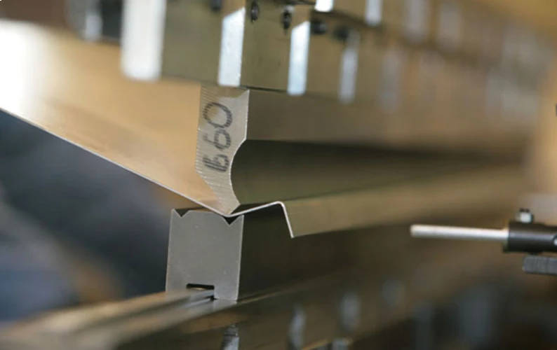
Understanding the fundamentals of sheet metal minimum bend radius begins with analyzing material behavior in the bending deformation zone. Under ideal pure bending conditions, a continuous strain gradient forms across the sheet cross-section from the inner to outer side. Inner material undergoes compressive plastic flow under die compression, while outer material is subjected to tensile stress.
The neutral layer, which separates the compression and tension zones, shifts inward and is directly related to the K factor. The stress distribution within this zone directly determines the success or failure of sheet metal bending: fracture occurs when tensile stress on the outer surface exceeds the material’s tensile strength or when strain surpasses its elongation limit. Therefore, any scientific bend radius calculation for sheet metal must first evaluate this strain distribution.
Core Influence Mechanism of Sheet Metal Thickness
In engineering decisions regarding sheet metal bend radius, sheet thickness is not a passive dimensional annotation but an active, governing physical variable. Its core influence permeates the entire process from manufacturability assessment to final forming.
Thickness as a Lever Arm
Sheet thickness (t) is the most critical geometric lever in bending mechanics. For a given sheet metal bending radius (R), the distance of the outermost fiber from the neutral layer (approximately t/2) determines the magnitude of tensile strain.
The fundamental strain equation ε ≈ t / (2R + t) clearly illustrates this lever effect: increased thickness directly leads to a proportional increase in outer strain. This explains why thin sheets can achieve smaller minimum bend radii for sharp corners, while thicker sheets of the same material require larger radii to prevent cracking. Thickness serves as the primary engineering variable linking material properties and process feasibility.
Thickness-to-Radius Ratio (t/R) as the Core Dimensionless Parameter
The thickness-to-radius ratio (t/R) serves as the core dimensionless engineering parameter linking sheet metal thickness to bending radius, quantitatively describing the severity of bending. A high t/R value indicates extreme strain and significant forming risks; conversely, a low t/R value signifies a gentle bend.
This parameter is critical for predicting fracture, wrinkling, and calculating neutral layer displacement (K-factor). A professional manufacturer should be able to explain the t/R value corresponding to their recommended sheet metal bending radius and demonstrate how this value is controlled within the material’s safe strain limit.
Magnification Effect of Thickness on Sheet Metal Bending Springback
The influence of thickness on sheet metal bending processes extends beyond cracking risks; it also significantly amplifies springback effects. Springback originates from the material’s elastic recovery upon unloading, with the recovery angle dependent on the sheet’s yield strength, elastic modulus, and sectional moment of inertia.
Since the sectional moment of inertia is proportional to the cube of thickness (I ∝ t³), even a slight increase in thickness leads to a substantial rise in elastic strain energy. This implies that for identical sheet metal bend radii and materials, thicker plates exhibit more pronounced angular springback and radius springback than thinner plates. Consequently, bend radius calculations for thick sheet metal must incorporate precise springback compensation models—typically achieved through finite element analysis or database-driven empirical formulas—rather than simply applying thin-plate process parameters.
Only 4 steps
online custom metal fabrication parts
Contact our experts team and experience the efficiency and economic benefits of digital metal fabrication services.
Upload Design Files
STL , STEP (.stp), IGES (.igs), (.ZIP), or PDF.
Also be a sample or an idea
Quote & Design Analysis
Instant factory quotes and DfM reports, the most reasonable solution.
Manufacturing Begins
Digital processes can initiate order tasks within 24 hours.
On-Time Delivery
Keeping delivery promises, approved by 3000+ Global Company buyers.
Calculation Correlation: The Mathematical Relationship System Between Sheet Metal Bend Radius and Sheet Thickness
From an engineering practice perspective, the correlation between sheet metal bend radius and sheet thickness is established through a quantifiable mathematical relationship system. This system transcends “empirical rules,” providing a verifiable tool for precise bend radius calculation for sheet metal.
Applicability and Limitations of Sheet Metal Rule-of-Thumb Bend Radius
Common industry rules-of-thumb, such as “the minimum bend radius for sheet metal in low-carbon steel equals the material thickness (1t), while stainless steel requires 2t,” provide quick reference points for preliminary design evaluations. These guidelines originate from extensive practical observations of the plastic properties of common materials, with their underlying logic corresponding to the typical permissible strain ranges characteristic of different material categories.
However, for rigorous engineering procurement, relying solely on bend radius for sheet metal rules of thumb carries risks. These rules fail to quantitatively account for specific material conditions (such as cold-rolled hardening levels or different alloy grades), bending direction, sheet rolling orientation, and surface quality requirements.
For instance, applying bend radius for sheet metal rules of thumb to high-strength steel or components requiring Grade A painted surfaces may result in micro-cracks along edges or visible impact lines. Consequently, while such rules serve as useful guides during conceptual design phases, the final sheet metal bend radius for manufacturing must be determined through more scientifically grounded calculations.
Core Principles of Scientific Calculation for Sheet Metal Bend Radius: K-Factor and Unfolded Length Calculation
In sheet metal engineering, the key to achieving precise manufacturing lies in the accurate calculation of unfolded length. At the heart of this calculation is the precise application of the K-factor. The K-factor is not an arbitrarily set constant; it is a critical engineering variable that integrates sheet metal bend radius, plate thickness, and material plastic behavior to determine the position of the neutral layer during the bending process.
Physical Significance and Engineering Definition of the K Factor
The K factor is a core coefficient in sheet metal unfolding calculations. Its engineering definition is: K = (t’ – Ri) / t, where t’ is the distance from the neutral layer to the inner surface, Ri is the inner bending radius, and t is the material thickness. It describes the degree of inward displacement of the neutral layer within the bending cross-section. An accurate K factor is essential for precise bend radius calculations in sheet metal and obtaining correct development lengths. It directly impacts blanking dimensions and the final product’s dimensional accuracy.
Dynamic Relationship Between K Factor and Thickness-to-Diameter Ratio (t/R)
A clear dynamic functional relationship exists between the K factor and the thickness-to-radius ratio (t/R). When t/R is very small, the neutral layer approaches the center of the plate thickness, and the K factor approaches 0.5. As t/R increases, the neutral layer shifts significantly toward the bend inner side, and the K factor decreases, potentially dropping to 0.3 or lower.
This relationship indicates that variations in sheet metal bending radius and thickness directly impact the developed dimensions. Therefore, calculations using a fixed K factor (e.g., 0.445) are only accurate within specific t/R ranges. For high-precision design or scientifically sound bend radius calculations for sheet metal, a dynamic K factor based on t/R must be employed.
K-Factor Tables in Engineering Practice
In established engineering practice, professional bend radius calculations for sheet metal rely on K-factor tables generated through experimentation or authoritative software. These tables typically plot K-factor values against thickness-to-radius ratios (t/R) or outer-diameter-to-radius ratios (t/Ro) as the x-axis, organized by material type or yield strength series.
Many CAD/CAM software packages compliant with ASME or ISO standards (e.g., SolidWorks, AutoForm) incorporate such validated databases. For critical components, manufacturers calibrate and validate sheet metal minimum bend radius and K-factor data through actual bending tests to ensure calculation accuracy.
Calculation of Sheet Metal Minimum Bend Radius
The calculation of sheet metal minimum bend radius aims to prevent cracking of the outer fibers due to excessive stretching. Its core formula is: R_min = (t / (2ε_max)) – t, where t is the thickness and ε_max is the maximum allowable strain of the outer fibers. This reveals that the sheet metal minimum bend radius is directly proportional to thickness and inversely proportional to material ductility. Therefore, suppliers should base sheet metal bending operations on specific material standards and professional bend radius calculations for sheet metal, rather than relying solely on experience.
Bend Radius Calculation for Sheet Metal and Simulation Technology
When sheet metal design involves high-strength materials, complex geometries, or stringent fatigue life requirements, traditional empirical formulas and static parameter tables increasingly reveal limitations in bend radius calculation. Advanced computational methods and digital simulation technologies in modern engineering practice enable a leap from “empirical estimation” to “scientific prediction.”

Bend Radius Calculation for Sheet Metal Based on Material Property Data
Accurate bend radius calculation for sheet metal begins with in-depth application of material properties, requiring manufacturers to utilize the material’s true stress-strain curve. Key parameters such as the work hardening index (n-value) and plastic strain ratio (r-value) significantly enhance the computational model’s accuracy in predicting strain hardening behavior and thinning resistance during sheet metal bending.
For instance, materials with higher n-values distribute strain more uniformly during bending, permitting larger minimum bend radii for sheet metal. Conversely, the r-value influences strain distribution between the width and thickness directions. Inputting these precise data points into theory-based forming limit models enables crack risk assessment for specific thickness-to-radius combinations, achieving data-driven safety in design.
Application of Finite Element Analysis (FEA)
Finite element analysis serves as the core tool for transitioning the study of sheet metal bend radius-thickness relationships from two-dimensional formulas to three-dimensional virtual validation. By establishing a digital simulation environment encompassing die design, holding force, and material models, FEA enables visualization of stress and strain distribution within the sheet metal, as well as material flow throughout the entire bending process.
Engineers can preemptively observe whether outer-fiber strain exceeds safe limits at specified sheet metal bend radii or whether wrinkling occurs on the inner side. More importantly, FEA enables highly accurate prediction of springback.
This simulation method is particularly crucial for bend radius calculations in sheet metal, especially for high-strength steel or complex multi-step bending operations. It significantly reduces physical trial-and-error, shortens development cycles, and ensures first-pass forming success rates.
Experimental Determination Method
Despite increasingly powerful simulation and computational models, experimental determination remains the cornerstone for validating bend radius calculations for sheet metal and obtaining the most reliable process parameters. Standard methods such as the V-bend test involve bending specimens of specific material thicknesses using a series of punches with varying tip radii.
By measuring the actual inner radius after bending, the springback angle, and inspecting the outer surface for cracks, the actual sheet metal minimum bend radius and precise K-factor or Y-factor for that material at that thickness can be reverse-engineered. These experimental data are used to calibrate material parameters and friction coefficients in FEA models, forming a closed-loop validation cycle of “calculation-simulation-experiment.”
Looking for a reliable custom sheet metal fabrication companies?
Talk To Supro MFG Expert Team
Contact us for competitive ex-factory prices,
and a full range of technical support services.
Conclusion
In summary, the relationship between sheet metal bend radius and material thickness is fundamentally a precision engineering equation defined by material mechanics, geometry, and process technology. Its core principles are quantified through the thickness-to-radius ratio (t/R) and dynamically varying K-factor. This necessitates that bend radius calculations for sheet metal cannot rely on the empirical rule of “1 times material thickness,” but must instead be based on specific material property data.
If you require sheet metal bending services, contact us immediately! Supro is a professional sheet metal bending manufacturer. Leveraging advanced equipment, extensive manufacturing experience, and a specialized engineering team, we provide perfect sheet metal bending solutions to over 3,000 companies worldwide, offering genuine manufacturer pricing.
We possess extensive expertise, technology, and advanced equipment, understanding the requirements and standards for sheet metal bending structural components across industries including agriculture, healthcare, automotive manufacturing, and aerospace. Supro operates 12 distinct sheet metal bending machines, enabling us to deliver one-stop sheet metal bending services to all industries while ensuring high-quality products, professional customer service, and on-time delivery.
If you have any questions or concerns about our sheet metal bending services, please contact us immediately. We will proactively meet all your project requirements!