

In the coordination between sheet metal part design and procurement, the principle of sheet metal minimum bend radius cannot be overlooked. Designers pursuing aesthetically sharp corners often encounter material cracking or uncontrollable springback during prototyping, leading to project delays, cost overruns, and quality risks.
Fundamentally, the sheet metal minimum bend radius is not a freely scalable CAD parameter or mere empirical value; it represents a critical constraint where material plasticity mechanics, forming process windows, and the part’s ultimate structural performance converge. Misinterpreting it as an adjustable detail post-design rather than a mandatory pre-design validation parameter is the root cause of sheet metal processing failures.
This article systematically analyzes the core variables of sheet metal minimum bend radius and provides engineering principles and verification frameworks directly applicable to design reviews and supplier quotations. It aims to bridge the gap between design and manufacturing, ensuring part manufacturability, structural integrity, and cost control. Correct application of these principles is the cornerstone for accurately calculating minimum bend radius for sheet metal and efficiently translating design intent.
Definition and Physical Essence of Sheet Metal Minimum Bend Radius
The sheet metal minimum bend radius represents a fundamental constraint on sheet metal manufacturing capability. Its determination depends not only on tooling but more critically on the material's inherent ductility. To accurately calculate the minimum bend radius for sheet metal, one must analyze this strain threshold by integrating alloy properties with grain orientation, thereby establishing an insurmountable boundary for feasible design.
Professional Definition of Sheet Metal Minimum Bend Radius
In engineering and procurement specifications, the sheet metal minimum bend radius specifically denotes a defined manufacturing boundary. It is defined as: the radius that can be reliably achieved through standard bending processes for a given material, thickness, and bending direction without inducing macroscopic cracks on the outer (tension) side of the sheet.
The numerical value of the minimum bend radius for sheet metal is not a design preference but an objective limit where material physics and process capability converge. A common misconception treats it as a simple geometric parameter freely adjustable in CAD software; in reality, it is a mandatory constraint guiding Design for Manufacturability (DFM). Failure to adhere to supplier-validated sheet metal minimum bend radius guidelines directly leads to cracking, scrap during trial production, and project delays/cost overruns caused by process redesign.
Micro-level Mechanical Explanation of Sheet Metal Minimum Bend Radius
To professionally calculate the minimum bend radius for sheet metal, one must understand the underlying material mechanics: bending deformation forces non-uniform plastic strain within the metal.
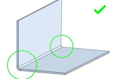
From a micro-mechanics perspective, the bending process causes tensile strain on the outer fibers and compressive strain on the inner fibers of the sheet. When the outer strain exceeds the material’s ultimate elongation, micro-cracks initiate and propagate, leading to macro-tearing.
Therefore, the core of accurately calculating the minimum bend radius for sheet metal lies in evaluating the maximum tensile strain the outer fibers can safely endure for a specific material grade and condition. The industry commonly expresses this as the “R/t” ratio (bend radius to thickness ratio), whose specific value is directly linked to the material’s cross-sectional reduction ratio and anisotropy.
Key Variables Affecting Sheet Metal Minimum Bend Radius
The sheet metal minimum bend radius is not a fixed value but a dynamic boundary determined by three major variables. To accurately calculate the minimum bend radius for sheet metal, a comprehensive analysis of material properties, geometric constraints, and process parameters is essential.
Sheet Metal Minimum Bend Radius and Material Properties
The inherent properties of the material are the primary factor determining the minimum bend radius for sheet metal. Each alloy type and its heat treatment condition corresponds to a specific ductility window, which directly defines the maximum plastic strain they can withstand without fracture.
Material Type and Condition
Bending properties vary significantly across different alloy systems. For instance, soft-tempered low-carbon steels (e.g., 1008/1010 SPCC) permit smaller R/t ratios (e.g., 0.5T) due to their high elongation.
Conversely, austenitic stainless steel (e.g., 304) possesses good toughness, but its high work hardening rate and low initial ductility typically require larger minimum bend radii for sheet metal (e.g., 1T to 2T). Procurement specifications must clearly state the full material designation and temper condition, as the bending limits and minimum bend radii for sheet metal differ significantly between different conditions (e.g., full hard, half hard, soft) for the same grade.
Trade-off Between Strength and Ductility
High-strength low-alloy (HSLA) or quenched-and-tempered steels achieve higher strength through alloying and heat treatment, often at the expense of ductility. Consequently, while part thicknesses may be reduced by using high-strength materials, the sheet metal minimum bend radius typically increases proportionally. Incorrectly applying low-carbon steel radii to high-strength steel parts is one of the most common causes of cracking during first-article trials.
Influence of Rolling Direction
During rolling, grains in sheet metal are elongated, resulting in anisotropic mechanical properties. Bending along the rolling direction (longitudinal) generally requires a smaller minimum bend radius than bending perpendicular to the rolling direction (transverse). For critical structural components or demanding bending conditions, designs must specify the orientation of the bend line relative to the sheet’s rolling direction. Neglecting this factor can result in edge cracking in some parts, even when the theoretical, safe minimum bend radius is met.
Sheet Metal Minimum Bend Radius and Material Thickness—Linear Proportional Relationship
Thickness is the most direct geometric variable affecting sheet metal minimum bend radius. The industry typically uses the dimensionless coefficient R/t (the ratio of inner radius to material thickness) for standardized discussion.
The sheet metal minimum bend radius and material thickness exhibit a linear proportional relationship: For a given material, the required minimum inner radius increases proportionally with increasing thickness. For example, if a material’s minimum bend radius is 1T, then for 1mm thick sheet metal, the minimum radius is 1mm; for 3mm thick sheet metal, the minimum radius is 3mm.
However, this linear relationship may deviate for extremely large or small thicknesses. When calculating the minimum bend radius for sheet metal, the R/t baseline must first be determined based on thickness, followed by adjustments for other variables.
Bending Process and Die Parameters
The theoretically calculated sheet metal minimum bend radius must be achieved through physical forming processes, and the selection of process equipment directly determines the formability limits.
The width of the lower die V-groove is a critical process variable controlling forming force and final radius. Groove width (V) is typically selected as 6 to 12 times the material thickness. An excessively narrow V-groove dramatically increases bending pressure and forces material deformation along sharper paths. While this may achieve a smaller minimum bend radius, it significantly elevates the risk of excessive stretching of outer fibers and tooling abrasion. Conversely, an overly wide V-groove leads to imprecise radius control and increased springback in the bent sheet metal.
The tip radius of the upper die (punch) directly shapes the inner radius of the formed part. Theoretically, the part’s inner radius is determined by the punch radius. However, in air bending, due to material elasticity, the actual formed inner radius is slightly larger than the punch radius. Therefore, to achieve a specific sheet metal minimum bend radius, a punch with a matching radius must be selected.
Air bending, bottom pressure bending, and impression bending exhibit differing capabilities in controlling the sheet metal minimum bend radius. Air bending offers the highest degree of freedom but exhibits significant radius consistency variation influenced by material batches; Bottom bending provides better control over angle and sheet metal minimum bend radius while reducing springback; Die bending achieves precise sharp corners by forcing material to fully conform to the die through extremely high localized pressure, but demands exceptional material ductility and subjects dies to immense stress.
Regardless of the chosen method, comprehensive consideration must be given to sheet metal minimum bend radius requirements, angular tolerances, production volume, and equipment capabilities.
Only 4 steps
online custom metal fabrication parts
Contact our experts team and experience the efficiency and economic benefits of digital metal fabrication services.
Upload Design Files
STL , STEP (.stp), IGES (.igs), (.ZIP), or PDF.
Also be a sample or an idea
Quote & Design Analysis
Instant factory quotes and DfM reports, the most reasonable solution.
Manufacturing Begins
Digital processes can initiate order tasks within 24 hours.
On-Time Delivery
Keeping delivery promises, approved by 3000+ Global Company buyers.
Design Principles and Calculating Minimum Bend Radius for Sheet Metal
Translating the principle of sheet metal minimum bend radius from theory to practice hinges on adopting a structured three-phase methodology. First, the established R/t ratio provides an initial conservative design baseline.
Second, to accurately calculate the minimum bend radius for sheet metal, it must be combined with the corresponding K-factor to achieve precise flat pattern creation. Finally, for high-strength or specialty alloy materials, this calculated value requires empirical validation to compensate for reduced ductility, ensuring final specifications meet both functional requirements and manufacturability.
General Empirical Rules and Industry Standard Starting Points for Calculating Minimum Bend Radius for Sheet Metal
The primary design principle for establishing sheet metal minimum bend radius is to establish a safety baseline based on validated industry empirical data. These universal rules typically provide values as multiples of material thickness (T) (R/t ratio), e.g., 1T for low-carbon cold-rolled steel, 1.5T for 5052-H32 aluminum alloy, and 2T for 304 stainless steel. These figures originate from long-term production practice, accounting for average material ductility and incorporating a safety margin to prevent cracking under typical manufacturing variations.
The universal rules of thumb for calculating minimum bend radius for sheet metal, aligned with industry standards, provide a critical starting point for preliminary design reviews and cost estimates. However, this “starting point” is not the final approved value. Direct application to final drawings carries risk, as it does not account for the uniqueness of specific material batches, extreme thicknesses, or critical application scenarios. Before confirming the final minimum bend radius for sheet metal, collaboration with the sheet metal bending manufacturer is required.
Relationship Between K-Factor-Based Flattening Calculations and Sheet Metal Minimum Bend Radius
Accurate calculation of the minimum bend radius for sheet metal must be synchronized with flattening length calculations, as both are tightly coupled through the K-factor. The K-factor defines the position of the neutral layer during bending and is central to calculating blank dimensions. The K-factor is not constant; it varies with the ratio of bending radius to material thickness (R/t).
A common design conflict arises when specifying an extremely small radius (e.g., 0.1mm) in the CAD model while using a default K-factor (e.g., 0.44) for the development calculation. This results in an excessively short development length, causing the actual bent part dimensions to exceed design values and leading to severe assembly interference.
Therefore, the final specified sheet metal minimum bend radius must precisely match the K-factor value used for CNC programming and blanking. Modifying the minimum bend radius for sheet metal necessitates a linked update to the unfolded model. This is a mandatory step to ensure dimensional tolerances.
Considerations for Minimum Bend Radius in Sheet Metal for High-Strength Steel and Special Alloys
For high-strength steel (such as AHSS), quenched and tempered steel, or certain special alloys (like titanium and copper alloys), applying universal rules of thumb to calculate the minimum bend radius for sheet metal becomes entirely ineffective. The core characteristic of these materials is the inverse relationship between strength and ductility. As tensile strength increases, the material’s ultimate elongation typically decreases, meaning the outer fibers can safely withstand less stress during bending. Consequently, the required sheet metal minimum bend radius increases significantly, potentially reaching 3T or higher.
The principle for calculating the minimum bend radius for sheet metal in such materials is “verify first, design later.” The approach involves conducting actual 90-degree bend tests on material samples sourced from the same batch as the production run before finalizing drawings, observing the critical cracking point. Procurement specifications must explicitly require sheet metal bending manufacturers to provide their verified sheet metal minimum bend radius data based on actual production conditions, incorporating this as part of the process approval.
Interrelated Design Rules for Sheet Metal Minimum Bend Radius and Common Failure Avoidance
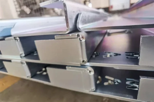
The established sheet metal minimum bend radius does not exist in isolation but forms the foundation of a series of critical and interrelated design rules. Neglecting these interdependencies is a primary cause of manufacturing failure, even when the bend radius itself is theoretically sufficient.
Minimum Distance Between Holes, Slots, and Edges from the Bend Line
To ensure the integrity of feature dimensions and positions after forming, all punched or laser-cut features (such as holes, slots, notches) must maintain a defined minimum distance from the bend line. When sheet metal bends, significant plastic strain and displacement occur within a wedge-shaped zone extending outward from the inner sheet metal minimum bend radius.
If a feature lies within this deformation zone, the surrounding material is unevenly stretched or compressed, causing geometric distortion of the feature. The extent of this deformation zone is primarily determined by two factors: the sheet metal minimum bend radius (R) and the material thickness (T). Larger radii and thicknesses result in a wider range of deformation influence.
A widely adopted empirical formula is: Minimum Edge Distance ≥ 1.5T + R. Here, T represents material thickness and R denotes the inside bend radius. For example, in a part with 2mm thickness and a minimum sheet metal bend radius of 2mm, any hole edge must be at least (1.5*2) + 2 = 5mm from the bend line. In space-constrained designs, this distance may be appropriately reduced, but manufacturability verification is required, and minor feature distortion must be accepted.
Avoiding Stress Concentration and Material Tearing During Bending
High stress concentration zones form where bend lines extend to sheet edges or intersect within confined areas. Material at these points experiences competing tensile and compressive stresses from multiple directions, making cracking highly likely even if the minimum bend radius is within safe limits.
The solution involves proactively incorporating stress relief structures during design. Pre-design a relief groove at the corner or edge where bend lines intersect. The groove width should be no less than the material thickness (recommended ≥1.5T), and its depth must ensure penetration into and beyond the plastic deformation zone defined by the sheet metal minimum bend radius and thickness, with depth > (R + T). The groove bottom should feature a curved transition to avoid creating new stress concentration points.
Tolerance Accumulation and Control in Multiple Bends
Tolerance management presents a systemic challenge in complex sheet metal parts with consecutive bends. Each individual bend inherently exhibits springback, influenced by slight variations in the sheet metal minimum bend radius, material mechanical properties, and tooling condition. These minor deviations propagate and amplify sequentially through subsequent bending operations, creating cumulative errors.
To mitigate this risk, designs should adhere to two principles: First, prioritize forming features that serve as subsequent positioning references during early bending stages. Second, selecting more stable bending radii with predictable springback (typically slightly larger than the minimum sheet metal bend radius) enhances process stability.
Sequencing Considerations for Welding and Bending
The sequence of welding and bending operations constitutes a critical process decision. The fundamental principle is: Whenever possible, complete bending before welding. The high temperatures generated during welding induce microstructural changes in the weld and its adjacent zone (the heat-affected zone, HAZ), typically resulting in increased hardness and a sharp decrease in ductility in this region. Subsequent bending performed on this brittle zone, even when using the theoretically calculated minimum bend radius for sheet metal, carries a high risk of inducing cracks at the weld location.
Looking for a reliable custom sheet metal fabrication companies?
Talk To Supro MFG Expert Team
Contact us for competitive ex-factory prices,
and a full range of technical support services.
Conclusion
In summary, the minimum bend radius for sheet metal is not merely a geometric parameter but the cornerstone of Design for Manufacturability (DFM). Calculating the minimum bend radius for sheet metal through a systematic approach requires integrating materials science, applied mechanics, and production practices to establish boundaries that ensure structural integrity and process reliability.
If you require sheet metal bending services, contact us immediately! Supro is a professional sheet metal bending manufacturer. Leveraging advanced equipment, extensive manufacturing experience, and a specialized engineering team, we provide flawless sheet metal bending services to over 3,000 companies worldwide, offering genuine manufacturer quotes.
As an advanced sheet metal bending manufacturer, we possess deep expertise, technology, and cutting-edge equipment. We understand the demands and standards for sheet metal bending parts across industries including agriculture, healthcare, automotive manufacturing, and aerospace. Supro operates 12 distinct sheet metal bending machines, delivering one-stop bending solutions across industries while ensuring high-quality products, expert customer service, and on-time delivery.
If you have any questions or concerns about our sheet metal bending services, contact us immediately. We will proactively meet all your project requirements!