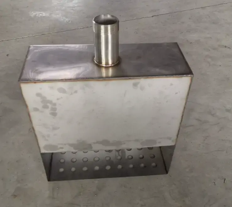
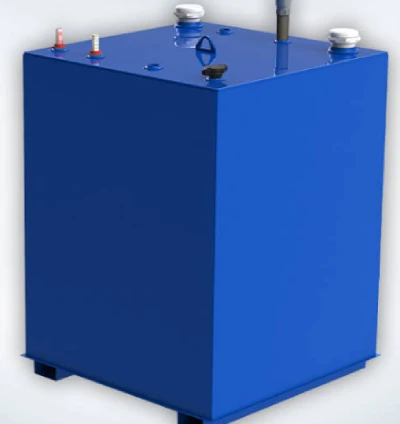



For metal oil tanks used in mobile or vehicle-mounted applications, the operating environment generates a unique set of cyclic load conditions that are rarely encountered in stationary storage tanks.
Liquid sloshing—that is, the inertial movement of fuel or engine oil during acceleration, braking, and vibrations caused by terrain—exerts repeated impact forces on the internal baffles. These dynamic pressures are directly transmitted to the fillet welds that secure the baffles to the metal oil tank shell, and they are the primary cause of premature fatigue failure.
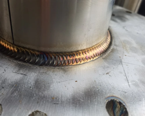
In welded structures, fatigue cracks almost invariably originate at the weld root—that is, the sharp geometric transition between the weld metal and the base metal—where the stress concentration factor is highest.
Although continuous fillet welds provide high structural rigidity, they hold the baffles in place and are unable to absorb energy; under cyclic shaking loads, the weld root acts as a fixed notch, thereby accelerating the initiation and propagation of cracks along the fusion line. The consequences extend beyond cracking of the baffle; they also lead to structural damage to the metal oil tank, typically manifesting as progressively worsening leaks. In severe cases, internal wear may occur, generating metal particles that can contaminate the downstream fuel system.
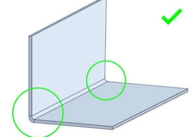
Therefore, preventive measures must address this issue on two levels: structural geometry and welding strategies for metal oil tanks. By employing corner chamfers—that is, chamfers or fillets on the baffles—the weld can be moved away from the high-stress corners of the tank where stress is most concentrated. Replacing rigid, continuous fillet welds with intermittent (skip) welds introduces controlled flexibility, allowing the baffles to absorb vibration energy through local elastic deformation rather than transferring the entire cyclic load to the weld root.
Combined with strict management of the root geometry of custom metal oil tank welds—such as improving the root transition radius through TIG trimming or controlled grinding—these design interventions can significantly extend the fatigue life of welded joints.
This article explores each of these strategies in detail, providing manufacturing-focused guidance for engineers and procurement professionals responsible for specifying custom metal oil tanks for demanding mobile applications.
Understanding the Fatigue Mechanism in the Welds of Metal Oil Tank Baffles
Fatigue cracks in the welds of metal oil tank baffles result from the cumulative effect of cyclic loads caused by the sloshing of liquid during transportation. The weld root acts as a natural stress concentration point, where local stresses far exceed the rated values.
Although continuous fillet welds offer high structural rigidity, they transmit each impact directly to this critical area and are unable to dissipate energy through controlled deformation. Understanding this mechanism is a prerequisite for effectively preventing fatigue cracking in the welds of custom metal oil tank baffles, as it provides the basis for modifying the geometry and adjusting the welding process.
The Role of Liquid Sloshing in Cyclic Loading
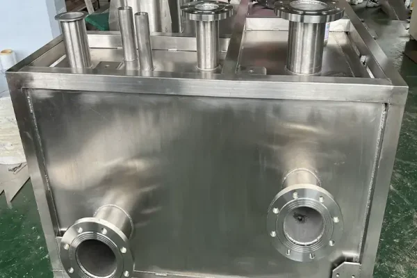
During transportation of mobile metal oil tanks, vehicle acceleration, deceleration, braking, and road vibrations cause continuous sloshing of the internal liquid, imposing periodic impact loads on the baffles. Physical bench tests have shown that during sloshing tests on a 350L tank, cracks and failures occur at the baffles and tank shell welds. This dynamic pressure is not a steady static load but acts cyclically on the weld area. Each sloshing impact adds another stress cycle at the weld, and after accumulating a certain number of cycles, fatigue damage occurs.
If sloshing loads are not accurately quantified during the design phase of a custom metal oil tank and the fatigue strength of the welds is not verified accordingly, cracks will be difficult to avoid during service.
Why Continuous Fillet Welds Accelerate Fatigue in Metal Oil Tanks
Rigid continuous fillet welding fully bonds the baffle plates to the tank wall, turning the weld toe into a geometrically discontinuous stress concentration point. Under sway impacts, the entire load is transmitted through the weld, resulting in local stresses at the weld toe that far exceed the nominal stress values.
More importantly, continuous welds lack any flexible redundancy—the baffle cannot absorb impact energy through slight deformation, and each impact cycle acts directly on the weld toe, which acts as a “fixed notch.” The residual stresses from the weld itself combine with operational loads, further elevating peak stress levels. Compared to flexible connection solutions that allow for limited elastic deformation, rigid full-penetration welding causes fatigue cracks to initiate earlier in custom metal oil tanks.
Actual Failure Modes of Custom Metal Oil Tanks
Failure typically begins with microcracks at the weld toe, which then propagate along the fusion line into the base metal. In one hydraulic system’s metal oil tank, after approximately 1.5 years of service, a through-wall crack appeared along the fusion line of the corner weld on the baffle plate’s side wall, resulting in oil leakage.
In more severe cases, crack propagation can lead to the complete detachment of the baffle from the weld. The loose component then slides inside the custom metal oil tank, causing wear and generating metal particles. These particles circulate with the oil into the engine’s fuel supply system, where they can clog the electronic fuel injectors, rendering the entire fuel injection system inoperable.
The consequences of fatigue cracking extend beyond the custom metal oil tank itself—it can trigger a chain reaction of failures in critical downstream components.
Are you looking for reliable & cost-effective
China Sheet Metal Fabricators
More than 150,000 OEM metal fabrication products delivered to 5,000+ global buyers.
And benefit from it!
Structural Design Strategies for Reducing Fatigue in Custom Metal Oil Tanks
To address fatigue issues in the welds of metal oil tank baffles, the primary consideration should not be welding parameters, but rather the geometry itself. Structural design interventions—such as relocating the weld away from high-stress corners of the metal oil tank through “corner notches,” and employing intermittent (skip) welding to introduce controlled ductility—can directly reduce stress concentrations at the weld root.
Unlike process adjustments, which can only alleviate but not eliminate the root cause, these geometric strategies free the baffles from rigid constraints, allowing them to dissipate energy through elastic deformation. The following measures are designed to address fatigue issues at their source.
Corner Notches—Eliminating Stress Concentration at Tank Corners
Placing baffle welds in the corner regions of custom metal oil tanks is one of the most common design errors. Tank corners are inherently areas of geometric discontinuity and already experience high edge stresses under sway loads. If the baffle is fully welded directly to the corner, the stress fields at the weld toe and the tank corner overlap, creating extremely high local stress peaks.
Applying chamfered corners to the baffles allows fluid to flow smoothly between compartments while reducing or eliminating joint fatigue issues. Finite element simulations have also confirmed that arc transitions significantly alleviate stress concentration, with the effectiveness directly related to the arc radius and position.
In engineering practice, Supro recommends limiting the notch width to no more than twice the plate thickness, with a maximum of 25 mm—a dimension sufficient to move the weld outside the high-stress zone without compromising the structural integrity of the baffle. For mobile metal oil tanks, this geometric modification adds virtually no manufacturing cost yet represents the most direct structural design measure for improving weld fatigue life.
Re-examining the Geometry and Connection Points of Metal Oil Tank Baffles
The geometric shape of the baffle directly determines the load transfer path at the welds. When a traditional flat-plate baffle is subjected to liquid impact, the entire load is concentrated and transferred through the welds to the tank wall; in contrast, curved or ribbed designs can convert part of the impact into thin-film stress within the plate, thereby reducing the bending stress component at the weld toe.
More importantly, the layout of the connection points between the baffles and the tank wall requires careful planning—avoiding the concentration of all welds in a single transverse cross-section, as this would otherwise turn that section into a “fatigue weak link” in the metal oil tank. When the straight edges of the baffles form line contact with the tank shell, stress concentrates along a single line on the shell, making it highly prone to cracking at the welds.
The recommended approach is to distribute the connection points and to provide oil-pass-through holes in the baffles to equalize the pressure differences between the various compartments. These geometric optimization measures work together to reduce the stress concentration factor at the welds of the metal oil tank, thereby delaying the initiation of fatigue cracks at the structural level.
Achieving Structural Flexibility Through Intermittent Welding
Rigid full-penetration welding completely bonds the baffle to the tank wall, causing swaying and impact forces to be transmitted directly to the toe of the weld without any attenuation. Skip welding (or intermittent welding), on the other hand, provides a completely different mechanical path.
By arranging intermittent weld segments around the perimeter of the baffle, the baffle gains space for slight elastic deformation in the unwelded areas, allowing it to absorb some of the vibration energy rather than converting all of it into stress cycles at the welds.
It should be noted that skip welding is not simply a matter of reducing the length of the weld bead—the start and end points of the weld are themselves sources of stress concentration, and the skip welding design must precisely calculate the proportional relationship between segment length, spacing, and plate thickness.
For metal oil tanks subjected to alternating loads, a properly designed segmented weld structure allows the baffle plate to maintain sufficient constraint strength while providing the necessary flexibility margin, thereby significantly extending the fatigue life of the entire welded joint.
Only 4 steps
online custom metal fabrication parts
Contact our experts team and experience the efficiency and economic benefits of digital metal fabrication services.
Upload Design Files
STL , STEP (.stp), IGES (.igs), (.ZIP), or PDF.
Also be a sample or an idea
Quote & Design Analysis
Instant factory quotes and DfM reports, the most reasonable solution.
Manufacturing Begins
Digital processes can initiate order tasks within 24 hours.
On-Time Delivery
Keeping delivery promises, approved by 3000+ Global Company buyers.
Welding Process Control and Quality Assurance for Custom Metal Oil Tanks
Welding process parameters directly determine the stress concentration factor at the weld toe and the distribution of residual stresses. For the welds on the baffle plates of metal oil tanks, even with a structurally sound geometric design, improper heat input or weld toe geometry can still significantly weaken fatigue strength.
Weld toe preparation, heat input control, and material matching are the three core variables in the welding process. This section will focus on the key control elements in the welding of metal oil tanks.
Management of Weld Toe Profile and Root Geometry
The geometric shape of the weld toe in custom metal oil tanks directly determines the stress concentration factor (SCF) at that location. The weld toe of a fillet weld is the transition zone between the weld metal and the base metal; its toe radius and undercut depth are the most critical parameters affecting the SCF. Relevant AWS technical documents clearly state that the weld toe itself acts as a stress riser.
The SCF value at the toe of a typical untreated fillet weld can reach 1.7 to 2.3—meaning that the local stress is nearly twice the nominal stress. Under cyclic loading, this geometric discontinuity becomes a preferred initiation site for fatigue cracks.
TIG dressing and grinding are two widely validated processes for treating the weld toe. TIG dressing improves the transition geometry and removes microdefects such as undercuts and slag inclusions by remelting the weld toe area; grinding mechanically refines the weld toe profile and smooths the transition.
Test specimens treated with TIG dressing or grinding exhibit a significantly longer crack initiation life than untreated “as-welded” specimens. For metal oil tanks subjected to alternating loads, performing weld toe treatment on the fillet welds of baffles during the manufacturing stage is a cost-effective measure that significantly improves fatigue life.
Heat Input Control and Residual Stress Management in the Welding of Metal Oil Tanks
Welding heat input directly affects the microstructure and properties of the heat-affected zone (HAZ) as well as the distribution of residual stresses around the weld. For T-joint fillet welds, significant transverse tensile residual stresses develop near the weld toe, which have an extremely adverse effect on fatigue cracking. The transverse tensile residual stresses at the weld toe in multi-pass, multi-layer welds are even higher than in single-pass welds, meaning that improper welding of metal oil tanks may actually exacerbate the risk of fatigue failure.
Welding sequence is another key variable affecting residual stress distribution. Selecting an appropriate welding sequence can effectively alter the residual stress distribution, thereby enhancing the fatigue strength of the welded structure.
When welding heat input or penetration depth is increased, transverse tensile residual stresses tend to decrease; however, excessively high heat input can lead to adverse effects such as grain coarsening in the HAZ—this represents a process window that requires careful balancing.
For the welds on the baffle plates of metal oil tanks, Supro quantifies the residual stress levels under different heat inputs and welding sequences through finite element analysis or experimental measurement during the process qualification phase, thereby determining the optimal combination of process parameters rather than welding arbitrarily based on experience.
Material Selection and Compatibility with Welding Consumables
Consistency between the baffle plate material and the metal oil tank material, as well as the compatibility between the welding consumables and the base metal, are fundamental prerequisites for the fatigue performance of the weld.
For welded structures with complex shapes or significant thickness, the internal stresses generated by the weld metal during cooling and contraction are high, resulting in a significant tendency to crack. In such cases, welding materials with good crack resistance must be selected—low-hydrogen electrodes and high-toughness electrodes are the standard choices for these applications.
When the strength of the welding consumables is lower than that of the base metal, the weld itself becomes the weak link in the structure; insufficient toughness, meanwhile, makes the weld prone to cracking under impact loads. Given the operating conditions of mobile metal oil tanks—where cyclic impacts and temperature fluctuations coexist—welded joints must not only possess sufficient static load strength but also demonstrate stable fatigue performance under alternating loads.
The selection of welding consumables should be based on the principle of matching the strength of the base metal, while also considering the impact toughness properties of the welding materials (such as the CVN impact value at -20°C or -40°C). In addition, low-hydrogen electrodes are crucial for controlling hydrogen-induced cold cracking—once such cracks form at the weld toe, they directly become the initiation sites for fatigue cracks.
Looking for a reliable custom sheet metal fabrication companies?
Talk To Supro MFG Expert Team
Contact us for competitive ex-factory prices,
and a full range of technical support services.
Inspection, Testing, and Lifecycle Considerations for Custom Metal Oil Tanks
For metal oil tanks subjected to cyclic vibration loads, quality assurance does not end with the completion of welding. A rigorous inspection and verification system—covering non-destructive testing (NDE) during the manufacturing process as well as fatigue life prediction during the design phase—is critical to ensuring that the details of the baffle welds will function reliably throughout the expected service life.
Standards such as ASME Section V, AWS D1.1, and API 650 specify the methods for conducting non-destructive testing (NDE) and the acceptance criteria. For surface defects at the root of welds in metal oil tanks, visual testing (VT) and penetrant testing (PT) serve as the first line of defense. These methods can detect undercut, overlap, surface porosity, and root cracks—defects that would otherwise become stress concentration points under cyclic loading.
For subsurface discontinuities—such as embedded porosity, slag inclusions, or lack of fusion below the surface—volumetric testing methods such as ultrasonic testing (UT) or radiographic testing (RT) are required. The detection limits of the NDE methods used directly determine the assumed initial crack size in subsequent fatigue life calculations.
In addition to inspections during the manufacturing phase of custom metal oil tanks, fatigue life predictions should be performed using recognized engineering methods. The structural hot-spot stress method recommended by the International Institute of Welding (IIW) has been widely applied to welded storage tank structures. Hot-spot stresses at critical weld legs are calculated using finite element analysis (FEA) and then compared with the IIW’s S–N curves—for example, the FAT-90 classification for steel fillet welds.
For fillet weld T-joints in oil tankers, studies combining finite element analysis (FEA) and fracture mechanics modeling based on Paris’s law have shown that properly designed joints can withstand more than 2.5 million cycles under actual design loads.
These validated prediction tools enable metal oil tank manufacturers to identify fatigue-critical areas prior to production and verify that custom metal oil tanks meet the design strength requirements specified in the standards.
Ultimately, the combination of targeted non-destructive testing during the manufacturing process and validated fatigue life predictions from the design phase provides procurement engineers with quantitative assurance that the baffle weld details of metal oil tanks can withstand severe cyclic operating conditions.
Conclusion
Fatigue in the partition welds of custom metal oil tanks is preventable—but prevention must be achieved through engineering design, not solely through inspection. The solution lies in the design phase: moving the weld away from high-stress corners by using corner notches; replacing rigid continuous fillet welds with intermittent skip welds to introduce controlled flexibility; and strictly controlling the root geometry of the weld through TIG trimming or grinding.
Combined with proven welding processes for metal oil tanks—heat input control, low-hydrogen consumables, and residual stress management—these measures collectively reduce stress concentration at the weld toe, which is the primary location for crack initiation.
Fatigue life predictions using the IIW Hot Spot Stress Method, validated through targeted non-destructive testing (NDE) during manufacturing, provide procurement engineers with quantitative evidence of reliability. As a result, custom metal oil tanks can withstand cyclic vibration loads throughout their expected service life, thereby reducing warranty claims and unplanned maintenance.
Supro is a specialized custom metal oil tank manufacturer. Leveraging advanced equipment, extensive manufacturing experience, and a professional engineering team, we provide comprehensive custom metal oil tank solutions to over 3,000 companies worldwide, along with genuine manufacturer quotes.
If you require technical specifications or wish to discuss OEM partnerships, please contact our engineering team.