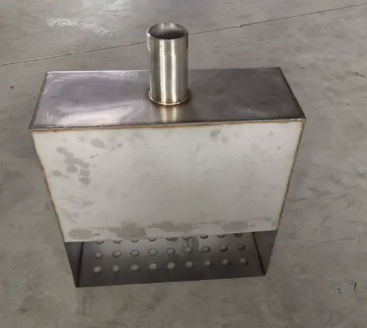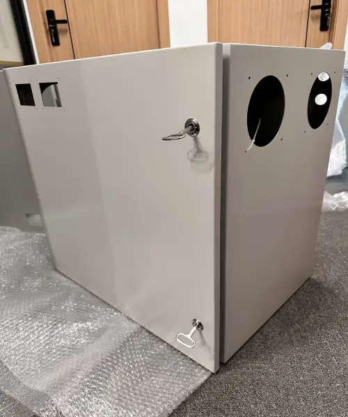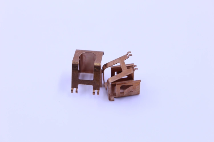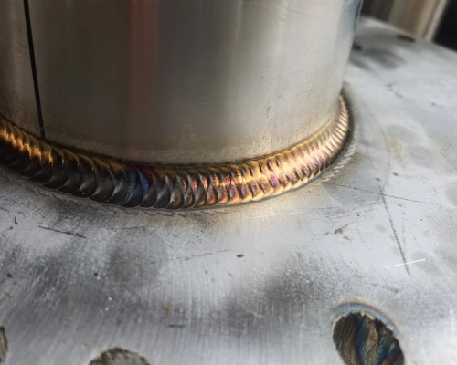

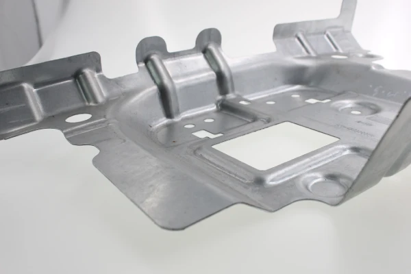
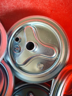
In the field of precision metal fabrication, matching part geometries and production volumes with the optimal sheet metal forming process directly determines the total cost of ownership. When part designs bypass early DFM (Design for Manufacturability) evaluations, mechanical engineers and global procurement teams often face budget overruns. Every geometric feature—from bend radii and flange heights to draw depths—directly limits your choice of forming processes.
Approximately 80% of a part’s manufacturing cost is determined during the initial design phase. Selecting an incompatible sheet metal forming method forces companies to bear unnecessary tooling amortization costs, exacerbates tolerance accumulation, and drives up the unit price. For example, specifying deep-drawing features on low-volume enclosures can result in unreasonable hard tooling costs, while relying on manual press brakes for high-volume bracket production can create a bottleneck in throughput.
To optimize precision sheet metal forming strategies, it is necessary to evaluate stress distribution, material springback, and production break-even points in advance. Matching CAD geometry with scalable sheet metal forming processes early on ensures dimensional repeatability, reduces scrap rates, and significantly lowers unit costs during both prototyping and mass production.
How Part Geometry Determines the Selection of Sheet Metal Forming Processes
Part geometry is the primary physical constraint in determining the selection of sheet metal forming methods. Geometric attributes—such as cross-sectional symmetry, the ratio of draw depth to width, and bend radius—determine the local stress state during processing, material flow limits, and die kinematics.
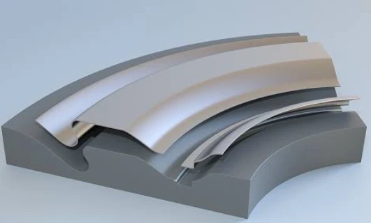
2D Flat Patterns and Linear Profiles: Laser Cutting, Turret Punching, and Roll Forming
For two-dimensional geometries and uniform linear profiles, the selection of an appropriate sheet metal forming process depends on feature density and profile length. Fiber laser cutting achieves extremely high contour accuracy without the need for expensive fixed-die tooling costs, making it ideal for low- to medium-volume flat blanks with complex contours. Turret punching excels when custom sheet metal forming requires the repeated processing of internal features—such as louver slots, perforations, or countersunk holes—using standard station dies.
However, for continuous linear profiles with a constant cross-section—such as structural channel sections or enclosure rails—sheet metal roll forming replaces discrete blanking. This process uses continuous deformation at linear speeds to achieve strict linear tolerances in high-volume production while minimizing scrap and strain hardening.
Complex 3D Contours and Enclosures: Press Brake Bending vs. Deep Drawing
The transition from flat blanking to 3D enclosures requires choosing between localized air bending and tensile-compressive sheet metal forming.
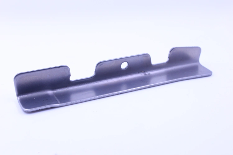
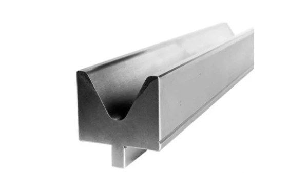
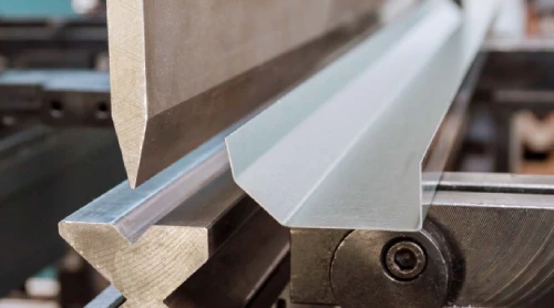
CNC press brakes can handle box-type geometries, structural brackets, and multi-flange chassis by performing sequential multi-axis bending. This method involves lower initial tooling costs but results in localized strain and introduces uncertainties associated with manual operation.
Conversely, seamless deep drawing transforms flat blanks into complex 3D shells or cylindrical cups via hydraulic presses and matched die sets. This sheet metal forming method forces the ductile material into the die cavity under controlled clamping pressure. Although deep drawing requires amortizing significant hard die costs, it eliminates secondary assembly welding and provides superior structural integrity for seamless shells in high-volume production.
Feature-Level Geometry Constraints: Hole Distances, Bend Radii, and Minimum Flanges
Micro-level geometric features impose strict mechanical constraints on every precision sheet metal forming operation to prevent structural degradation. Maintaining a minimum bend radius—typically 1.0 to 1.5 times the material thickness (depending on the yield strength)—prevents cracking of the outer fibers during the bending process.
The placement of features relative to the bend line is equally critical; Holes or notches located within 2.5 times the material thickness of the bend radius will undergo plastic deformation during custom sheet metal forming. Additionally, minimum flange height requirements (typically 4×thickness plus bend radius) ensure the workpiece fully engages the die without slipping. Incorporating proper bend relief notches prevents localized tearing at sheet intersections, safeguarding part dimensions and reducing scrap rates across all production volumes.
The Impact of Production Volume on Sheet Metal Forming Process Economics
Production volume determines the financial amortization curve and capital equipment configuration for precision sheet metal forming. Annual production volume dictates whether a flexible, lower-tooling-cost manufacturing method or a capital-intensive, high-throughput dedicated tooling system should be adopted to achieve the optimal total cost per unit.
Metric / Parameter | Low-Volume (< 1,000 pcs) | Mid-Volume (1,000 – 10,000 pcs) | High-Volume (> 10,000 pcs) |
Primary Process | Laser Cutting + Press Brake / Soft Tooling | Hybrid (Laser-Punch Combo + Single Dies) | Progressive Die / Hard Stamping |
Average NRE Tooling Cost | $0 – $1,500 | $2,500 – $10,000 | $15,000 – $60,000+ |
Relative Piece-Part Cost | High (Baseline: 100%) | Moderate (~35% – 50% of Baseline) | Very Low (~10% – 20% of Baseline) |
Tooling Amortization Share | Negligible / Low Impact | Moderate Impact | Very Low per Unit (Rapid ROI) |
Labor & Handling Contribution | High (Manual setup & position) | Medium (Semi-automated lines) | Minimal (Fully automated press feed) |
Cycle Time per Part | 2 – 10 Minutes | 15 – 60 Seconds | 0.5 – 3 Seconds (High Line Rate) |
First-Article Lead Time | 2 – 5 Days | 2 – 4 Weeks | 4 – 8 Weeks (Die Build & T1 Prove-out) |
Low-Volume & Prototyping (< 1,000 units): Flexible Tooling Solutions
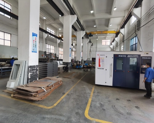
For low-volume production runs and prototyping of fewer than 1,000 units, flexible sheet metal forming solutions with the lowest non-recurring engineering (NRE) costs should be adopted to save money. By combining CNC fiber laser cutters with multi-axis press brakes, expensive custom hard dies can be avoided. Soft tooling solutions—such as 3D-printed polyurethane molds, modular universal dies, or soft steel inserts—enable the creation of localized sheet metal forming features (such as ribs or louvered structures) without requiring substantial upfront investment.
Although the unit cost remains relatively high due to labor costs and longer cycle times, the avoidance of long-term equipment setup amortization helps keep the total project cost low. This flexible custom sheet metal forming solution enables rapid design iterations, shortens time to market, and reduces financial risk during the initial product launch or pilot production phases.
Mid-Volume Production (1,000 – 10,000 units): Hybrid Fabrication Techniques
Mid-volume production ranging from 1,000 to 10,000 units represents a critical transition phase where hybrid sheet metal forming strategies achieve cost-per-part optimization. Manufacturers combine automated laser-punch combination machines with single-stage compound or form dies. This hybrid sheet metal forming method approach utilizes standard punch stations for flat perimeters while deploying simple hard tooling for specialized forms, offsets, or drawn features.
By replacing manual press brake handling with semi-automated single-station stamping presses, cycle times drop significantly without incurring the massive capital expenditure of fully integrated multi-station tooling. Procurement teams benefit from scalable production throughput, consistent part-to-part repeatability, and balanced NRE amortization that protects working capital during mid-tier manufacturing ramps.
High-Volume Production (> 10,000 units): Progressive Die Stamping
Sustained high-volume production exceeding 10,000 units justifies heavy NRE capital expenditure by leveraging high-speed progressive die sheet metal forming. A progressive die integrates multiple sequential operations—including blanking, piercing, coining, and multi-stage bending—into a single automated feed line. Sheet coil stock feeds through consecutive die stations with every stroke of the stamping press, completing complex parts at high line rates.
The substantial initial hard tooling investment amortizes rapidly over high unit volumes, driving piece-part costs to minimal levels. Additionally, fully automated progressive sheet metal forming minimizes manual labor, eliminates inter-process inventory, and delivers exceptionally tight tolerance control across multi-thousand-part production runs.
Only 4 steps
online custom metal fabrication parts
Contact our experts team and experience the efficiency and economic benefits of digital metal fabrication services.
Upload Design Files
STL , STEP (.stp), IGES (.igs), (.ZIP), or PDF.
Also be a sample or an idea
Quote & Design Analysis
Instant factory quotes and DfM reports, the most reasonable solution.
Manufacturing Begins
Digital processes can initiate order tasks within 24 hours.
On-Time Delivery
Keeping delivery promises, approved by 3000+ Global Company buyers.
Matrix for Selecting Sheet Metal Forming Processes
Selecting the optimal sheet metal forming process requires striking a balance between the initial non-recurring engineering (NRE) tooling investment and per-unit manufacturing efficiency. Complex 3D contours and deep-draw geometries naturally call for the use of a complete set of dies, while 2D flat contours and uniform linear grooves are better suited for a laser-bending combination or a sheet metal roll forming production line.
However, production volume remains the ultimate key factor in determining economic viability. Although CNC laser cutting and air bending eliminate upfront hard tooling costs, their longer cycle times per part can lead to excessive costs as production volume increases. Conversely, progressive stamping, while requiring significant initial capital investment, reduces per-unit labor and processing costs to negligible levels during high-volume production.
The engineering matrix below evaluates standard sheet metal forming solutions in terms of geometric constraints, capital expenditure, and production scalability.
Forming Process | Geometric Suitability | Break-Even Volume Range | Tooling Cost Investment (USD) | Initial Lead Time |
Laser Cutting + Press Brake | 2D Flat Patterns, Structural Brackets, Multi-Flange Enclosures | 1 – 1,000 pcs | $0 – $500 (Flexible/Soft Tooling) | 2 – 5 Days |
Perforated Panels, Internal Louvers/Knockouts, Flat Sheets | 500 – 3,000 pcs | $500 – $3,000 (Standard Station Dies) | 3 – 7 Days | |
Roll Forming | Long Continuous Linear Profiles, Constant Cross-Sections | > 5,000 Linear Meters | $15,000 – $50,000+ (Custom Roll Sets) | 4 – 8 Weeks |
Single-Stage / Compound Stamping | Medium-Complexity 3D Stampings, Shallow Drawn Shells | 1,000 – 10,000 pcs | $2,500 – $8,000 (Single Dies) | 2 – 4 Weeks |
High-Complexity 3D Parts, Multi-Feature Small/Medium Stampings | > 10,000 pcs | $10,000 – $50,000+ (Hard Tooling) | 4 – 6 Weeks | |
Seamless Cylindrical Cups, Box Enclosures, Complex Shells | > 5,000 pcs | $15,000 – $60,000+ (Matched Draw Dies) | 5 – 8 Weeks |
Practical DFM Guidelines for Preventing Sheet Metal Forming Defects
To prevent defects in the sheet metal forming process, proactive DFM control measures must be implemented during the design phase. By managing material flow, stress concentration, and anisotropic properties, issues such as cracking, wrinkling, and dimensional instability in complex forming features can be directly mitigated.
Managing Material Springback Across High-Strength Alloys
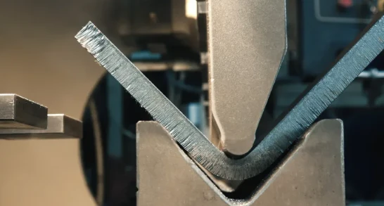
Controlling dimensional changes in high-strength alloys during custom sheet metal forming hinges on understanding the phenomenon of elastic recovery (i.e., springback). Higher yield strengths increase elastic strain energy, leading to significant elastic recovery after unloading. To achieve predictable geometric tolerances in precision sheet metal forming, Supro’s engineering team employs finite element analysis (FEA) simulations to precisely calculate the material’s springback behavior.
Incorporating overbending die geometries directly offsets dimensional deviation. Placing structural stiffening ribs or indentation lines along the bend radius alters the local residual stress distribution, thereby effectively locking the plastic deformation zone in place. Furthermore, optimizing the clamping force during the dynamic forming cycle minimizes angular deviation, ensuring that high-strength structural stamped parts consistently meet strict CAD tolerance requirements during mass production without the need for extensive manual secondary processing.
Eliminating Cracking and Wrinkling in Deep-Drawn Shells
To prevent structural failure in deep-drawn sheet metal forming, a balance must be maintained between circumferential compressive stress and longitudinal tensile stress. Cracking occurs when the tensile stress in the side walls exceeds the material’s tensile strength; conversely, wrinkling in the flange area occurs when excessive circumferential compressive stress causes local elastic buckling.
To optimize deep-drawn sheet metal forming, designers must refer to the Forming Limit Diagram (FLD) to determine safe strain thresholds. Maintaining a minimum radius ratio of 4.0× the material thickness between the punch and die reduces sharp stress concentrations. Applying dynamic hydraulic blank-holder pressure controls material flow into the die cavity, suppressing flange wrinkling while preventing excessive thinning.
Additionally, using high-performance synthetic lubricants reduces the coefficient of friction, thereby preventing local seizing and die wear during high-volume production.
Looking for a reliable custom sheet metal fabrication companies?
Talk To Supro MFG Expert Team
Contact us for competitive ex-factory prices,
and a full range of technical support services.
Supro MFG Engineering Support: Optimizing Your Sheet Metal Designs
At Supro MFG, our engineering team closely integrates CAD design concepts with the actual sheet metal forming process. By combining early-stage DFM analysis with scalable die architecture, we help global OEMs avoid costly design revisions and optimize cost-effectiveness per unit.
Early-Stage DFM Review
Collaborating with Supro MFG during the early stages of design ensures that your CAD geometry aligns perfectly with the actual sheet metal forming process. Our engineering team conducts a rigorous DFM evaluation, using advanced finite element analysis (FEA) simulations to identify potential stress concentrations, thinning limits, and springback behavior before cutting tool steel.
By identifying tight clearances between holes and bends, insufficient bend radii, or unachievable draw depths early on, we recommend subtle geometric modifications to optimize the custom sheet metal forming process while preserving the design intent.
This proactive collaboration prevents costly pre-production tooling rework, shortens prototyping cycles, and provides procurement teams in North America and Europe with fully validated, manufacturable drawings. Ultimately, our early-stage DFM support ensures dimensional repeatability, reduces supply chain risks, and locks in the optimal unit price well before full-scale production begins.
Scalable Tooling & Fabrication Strategies from Prototype to Mass Production
Supro MFG delivers seamless production scalability by tailoring sheet metal forming tooling strategies directly to your evolving volume demands. For initial product launches and small-batch orders, we utilize flexible fiber laser cutting and modular soft tooling to minimize upfront non-recurring engineering (NRE) costs.
As annual demand scales into mid-tier volumes, our engineers seamlessly transition parts to semi-automated single-stage stamping presses or hybrid forming stations. For high-volume OEM programs, we design and build precision progressive dies engineered for line-rate continuous sheet metal forming. This progressive tooling architecture integrates blanking, piercing, and complex multi-stage bending into a single press stroke.
By managing the entire lifecycle—from prototype soft tooling to hardened high-volume die sets—Supro MFG protects your capital investment and maintains strict ISO-compliant quality standards.
For technical specifications, customized project solutions, or OEM partnership inquiries, please contact Supro immediately. Our professional engineering team is ready to provide you with a tailored application solution.