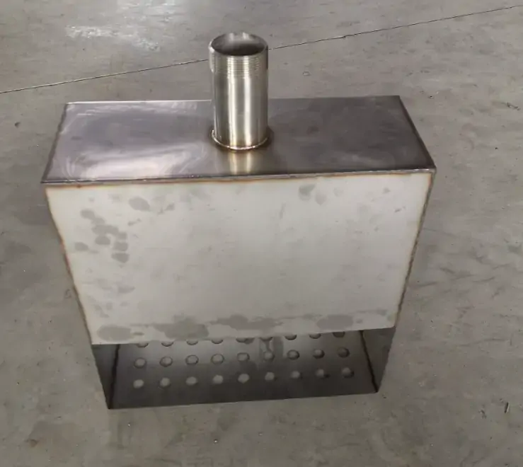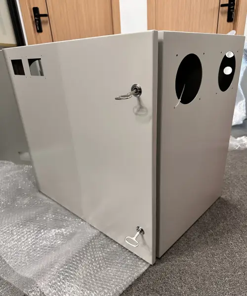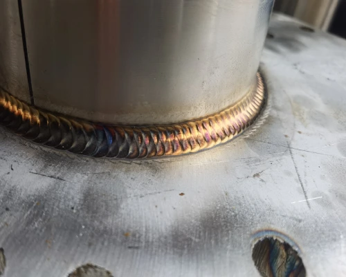

For metal water tanks, hydrostatic pressure is the most fundamental yet most frequently underestimated structural load. Hydrostatic pressure increases linearly with liquid depth—the pressure exerted on the bottom of the tank is significantly higher than that on the upper sections.
This physical characteristic directly dictates the need for non-uniform wall thickness in the design. Under hydrostatic pressure, cylindrical metal water tanks primarily experience circumferential stress; if this stress is not accurately calculated, it can cause the tank wall to bulge outward in the bottom region. Existing cases of engineering failures indicate that metal water tanks with insufficient wall thickness design can experience permanent bulging of more than 2 mm in the bottom wall under full-load conditions—this plastic deformation not only compromises structural integrity but also accelerates the initiation of stress concentrations and fatigue cracks during subsequent use.
Hydrostatic pressure control for custom metal water tanks must begin at the design stage: shell thickness calculations should be performed in accordance with standards such as API 650 or ASME Section VIII Division 1; deformation prediction and structural optimization should be completed prior to manufacturing using finite element analysis (FEA); and structural rigidity should be enhanced with precision-formed baffles or ribs—rather than simply relying on increased plate thickness to counteract hydrostatic pressure loads.
Understanding Hydrostatic Pressure Loads in Metal Water Tank Design
Hydrostatic pressure loads are the fundamental physical constraint in the structural design of custom metal water tanks—the pressure generated by gravity when a liquid is at rest increases linearly with depth, with the bottom region bearing the maximum load, and hoop stress is the dominant mechanical parameter in calculating the wall thickness of cylindrical vessels. The structural integrity of a metal water tank depends on the precise quantification of this load distribution.
Physical Principles of Hydrostatic Pressure—Load Distribution Varying with Depth
The hydrostatic pressure exerted on the inner walls of metal water storage tanks is generated by the weight of the liquid itself, and its magnitude is linearly proportional to the depth of the liquid. The basic equation for hydrostatic pressure is dp/dh = ρg, where ρ is the density of the liquid and g is the acceleration due to gravity.
This means that the pressure exerted on the bottom of a metal water tank is significantly higher than that in the upper regions—for example, with a 10-foot water column, the pressure at the top is zero, while at the bottom it reaches 624 psf.
This triangular load distribution, which increases linearly with depth, forms the physical basis for tank wall thickness design: the bottom wall requires the greatest cross-sectional thickness because it bears the maximum hydrostatic pressure, while the upper sections can be correspondingly thinner. The API 650 standard is based on this principle and employs a stepped-wall design method, in which the thickness of each section of the shell is calculated independently based on the height of the water column above it.
Hoop Stress and Longitudinal Stress in Cylindrical Metal Water Tanks
Under hydrostatic pressure, cylindrical metal water tanks experience two primary stress components: hoop stress and longitudinal stress.
Hoop stress is the dominant stress, and its calculation formula is σ_θ = P·D/(2t), where P is the internal pressure, D is the tank diameter, and t is the wall thickness.
Longitudinal stress is calculated as σ_a = P·D/(4t), which is exactly half of the hoop stress.
This mechanical relationship provides direct guidance for the manufacture of custom metal water tanks: since hoop stress is twice that of longitudinal stress, the tank is subjected to greater tensile loads in the hoop direction. Therefore, hoop strength must be ensured through proper material selection and wall thickness control to prevent structural failure caused by excessive tensile loads.
Comparison of Flat-Panel Walls and Cylindrical Geometries
In the design of custom metal water tanks, the choice of geometric configuration has a decisive impact on structural efficiency. The way a flat-plate wall structure resists hydrostatic pressure relies on bending—stress is carried by the plate thickness and moment of inertia, as given by the formula σ = Mc/I.
In contrast, a cylindrical shell resists pressure through membrane tension, where stress is related to the radius and wall thickness, as given by the formula σ = Pr/t. This fundamental difference allows cylindrical shells to make more efficient use of material strength, resulting in greater load-bearing capacity. In other words, for a flat-plate wall structure to withstand the same hydrostatic pressure as a cylindrical metal water tank, it would require significantly thicker plates or a dense rib structure, leading to a substantial increase in material costs and manufacturing complexity.
For the manufacture of large-capacity metal water tanks, cylindrical geometry represents the optimal balance between structural efficiency and material economy.
Only 4 steps
online custom metal fabrication parts
Contact our experts team and experience the efficiency and economic benefits of digital metal fabrication services.
Upload Design Files
STL , STEP (.stp), IGES (.igs), (.ZIP), or PDF.
Also be a sample or an idea
Quote & Design Analysis
Instant factory quotes and DfM reports, the most reasonable solution.
Manufacturing Begins
Digital processes can initiate order tasks within 24 hours.
On-Time Delivery
Keeping delivery promises, approved by 3000+ Global Company buyers.
Metal Water Tank Design Based on Finite Element Analysis (FEA): Predicting Deformation Before Manufacturing
Finite element analysis (FEA) enables metal water tank manufacturers to predict the structure’s response to hydrostatic pressure before cutting the steel. By simulating triangular load distributions in a CAD environment, FEA can identify areas of stress concentration and predict deformation. ASME Section VIII Division 2 has incorporated FEA into the “design by analysis” methodology, shifting the design verification of metal water tanks from empirical formulas to precise numerical predictions.
Finite Element Analysis as a Verification Tool in the Design Phase
In an FEA model for a metal water tank, engineers must define material properties (modulus of elasticity, Poisson’s ratio, yield strength), boundary conditions (bottom fixed constraint), and load cases. For large-capacity water tanks, 2D quad or shell elements (such as SHELL181 or SHELL281) can achieve accurate discretization of the shell structure. FEA reveals local stress concentrations and nonlinear responses that are difficult to capture through traditional manual calculations, providing quantitative basis for the wall thickness design and rib placement of custom metal water tanks.
Simulating Hydrostatic Pressure Conditions in CAD Projects
Simulating hydrostatic pressure in metal water storage tanks requires establishing load boundary conditions in the CAD environment that match the physical conditions. Hydrostatic pressure is linearly distributed along the depth of the tank (dp/dh = ρg), with the bottom region experiencing the maximum pressure and the top region approaching zero.
In general-purpose FEA platforms such as ANSYS Workbench, this triangular load distribution can be applied directly using the built-in hydrostatic pressure load module—engineers need only specify the liquid level height and liquid density, and the solver automatically generates a pressure field that varies with depth along the normal to the wall surface.
For a Metal Water Tank with a stepped-wall design, the FEA model must assign corresponding thickness values to each section of the shell to accurately capture the stress distribution characteristics at the points where wall thickness changes abruptly. The validity of the simulation results depends on mesh quality and the appropriateness of the boundary conditions—poor mesh quality may mask local stress peaks, leading to erroneous design judgments.
Finite Element Analysis Results—Stress Distribution Plots and Deformation Predictions
The post-processing output of the FEA for a custom metal water tank primarily includes stress distribution contour plots and displacement deformation plots; both must be interpreted in conjunction to assess structural integrity.
Stress distribution maps visually display the distribution of hoop stress and meridional stress along the tank’s height and wall thickness. Deformation prediction maps quantify the radial displacement of the tank wall under hydrostatic pressure—when the metal water tank is fully loaded, the bottom wall may exhibit characteristic “elephant-foot” bulging deformation. If the deformation predicted by FEA exceeds the elastic range, it indicates that the wall thickness or rib arrangement is insufficient and must be adjusted during the design phase.
Metal water tank manufacturers should use FEA results as the core basis for design reviews, using quantified stress and deformation data to guide optimization decisions regarding wall thickness allocation and rib layout.
Are you looking for reliable & cost-effective
China Sheet Metal Fabricators
More than 150,000 OEM metal fabrication products delivered to 5,000+ global buyers.
And benefit from it!
Material Thickness Selection and Structural Optimization for Metal Water Tanks
Selecting the wall thickness for a metal water tank involves striking an engineering balance between structural strength and material cost. Hydrostatic load-bearing capacity increases linearly with wall thickness—the formula t = P·D/(2·S·E) clearly defines the quantitative relationship among design pressure, diameter, allowable stress, and welding efficiency.
However, some manufacturers select sheet metal with excessively large negative tolerances to reduce costs, resulting in actual thicknesses below nominal values. This implicitly reduces the load-bearing margin of the metal water tank. API 650 and ASME Section VIII provide standardized engineering frameworks for shell thickness calculations.
Wall Thickness of Metal Water Tanks and Its Relationship to Hydrostatic Load-Bearing Capacity
The wall thickness of metal water storage tanks is the key parameter determining their hydrostatic load-bearing capacity—the load-bearing capacity increases linearly with wall thickness. For cylindrical structures, hoop stress is the dominant stress component. The API 650 standard employs a stepped-wall design method—dividing the tank into multiple shell sections (courses), with the thickness of each section calculated independently based on the height of the liquid column above it.
For metal water tanks with a diameter less than 60 m, API 650 specifies the use of the “1-foot method”: a design point is selected 0.3 m (1 ft) above the bottom of each shell course, and the minimum thickness required for that course is calculated based on this point. The greater of the design thickness t_d and the hydrostatic test thickness t_t is adopted as the final wall thickness. Understanding this quantitative relationship between thickness and pressure is a prerequisite for ensuring that the structural design of custom metal water tanks balances safety and material economy.
Issues with Negative Wall Thickness Tolerances
In the manufacturing of metal water tanks, some suppliers select steel plates with excessively large negative tolerances—that is, plates whose actual thickness is less than the nominal thickness—in order to reduce material costs. This practice has cumulative consequences for the wall thickness calculations of metal water tanks: if the actual thickness of the sheet metal is 10% lower than the nominal value, the load-bearing margin is correspondingly reduced by approximately 10%, a margin that is originally intended to account for manufacturing errors, localized stress concentrations, and corrosion-induced thinning during long-term use.
The API 650 standard explicitly requires that a corrosion allowance (CA) be considered in shell thickness calculations, typically set at 3 mm or higher.
When sheets with negative tolerances are used in the manufacture of metal water tanks, this corrosion allowance is substantially eroded—meaning the tank loses its design-intended safety margin from the very beginning of operation.
As a professional metal water tank manufacturer, Supro clearly indicates the actual measured thickness values in our material certificates and verifies each section against the design thickness.
Design Framework for Shell Thickness Calculations in API 650 and ASME Section VIII
The wall thickness design of metal water tanks must follow a standardized engineering framework. API 650 is the industry benchmark standard for the design of welded steel storage tanks, specifying methods for calculating shell thickness and acceptance criteria.
This standard provides three methods for calculating shell thickness: the 1-foot method (applicable to tanks with a diameter less than 60 m), the variable-design-point method (VDM, applicable to tanks with a diameter greater than 60 m), and the linear analysis method. The formula for calculating the design thickness is t_d = (4.98·D·(H-0.3)·G)/S_d + CA, where D is the tank diameter, H is the liquid level height, G is the specific gravity of the liquid, and S_d is the allowable design stress.
ASME Section VIII Division 1 UG-27 provides another set of design rules for calculating the shell thickness of pressure vessels—when P < 0.385·S·E, the thin-wall formula is used to calculate the minimum wall thickness under hoop stress. The ASME method introduces a weld joint efficiency factor E—for longitudinal welds that have not undergone radiographic testing, the value of E can be as low as 0.7, resulting in a 43% increase in the required wall thickness.
For metal water tank manufacturers, the choice of which standard framework to apply depends on the tank’s intended use, pressure rating, and the specific requirements of the customer’s industry.
Why choose Supro MFG's Custom Sheet Metal Fabrication Services
Provide the most cost-effective cost solution for manufacturing and assembling products, expanding product competitiveness.
a technical team specializing in custom shell manufacturing for more than 30 years.
Advanced Manufacturing Equipment: Industry-leading custom metal enclosure manufacturer with in-house sheet metal, die casting, precision machining workshops, and surface coating workshops.
ISO 9001-2015, PPAP III level, RoHS, NEMA, CE and other certified production standards.
24H*7 online English technical support: The professional English team responds quickly to users’ technical questions online at any time.
help users from product design, prototype, batch manufacturing, surface treatment, assembly and packaging, transportation and a series of value-added services.
With in-house mechanics and chemistry laboratories, it can quickly monitor manufacturing process quality control to ensure the delivery of high-quality products.
Accept to sign NDA documents to ensure that customers’ product information is protected.
Door-to-door delivery in customizable secure packaging after complying with the delivery details agreed with the customer.
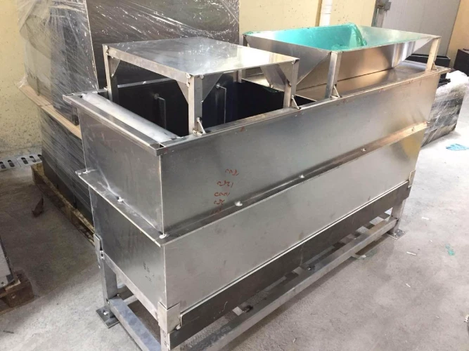
Precision-Formed Reinforcements for Custom Metal Water Tanks
Precision-formed stiffeners (ribs) enable metal water tanks to achieve a significant increase in structural rigidity through controlled material increments. By precision bending flat plates into load-bearing profiles with specific cross-sectional geometries—such as L-shaped, C-shaped, or corrugated sections—stiffeners help distribute hydrostatic loads through membrane tension or bending stress. The API 650 standard provides engineering calculation methods for the spacing and section modulus of stiffeners.
The Role of Baffles and Ribs in Resisting Wall Bulging
Under hydrostatic pressure, the bottom wall of a metal water tank bears the maximum load and is prone to characteristic “elephant-foot” bulging deformation. Baffles and ribs, acting as discrete reinforcing elements, share the hoop stress borne by the tank wall by transferring a portion of the load to their own cross-sections in the form of bending stress.
The API 650 standard provides calculation methods for rib spacing and section modulus—during design, it must be ensured that the actual moment of inertia of the ribs exceeds the minimum moment of inertia specified by the standard. As a professional metal water tank manufacturer, Supro’s experience shows that ribs are not merely additional components, but load-bearing elements subject to precise mechanical calculations; their arrangement density and cross-sectional dimensions must be matched to the tank’s diameter, wall thickness, and liquid level height.
Precision Bending of Reinforcement Profiles
Reinforcements for metal water tanks typically feature cross-sectional shapes such as L-shaped, C-shaped, or WT profiles. These profiles are formed through precision bending or roll bending, transforming flat plates into load-bearing members with specific section moduli—their moments of inertia and cross-sectional areas must meet the quantitative requirements of API 650.
The section modulus of a stiffener determines its ability to resist bending deformation, and the calculation formula is based on fundamental principles of structural mechanics. For cylindrical metal water tanks, stiffeners are typically annular and require a rolling process to achieve precise arc curvature; for rectangular tanks, straight-line bending is used. The connection between the stiffeners and the tank wall is typically achieved through continuous or intermittent welding.
The forming accuracy of the stiffeners directly determines the effectiveness of the reinforcement—excessive deviations in cross-sectional dimensions will result in insufficient actual moment of inertia, thereby weakening their load-bearing capacity.
Arrangement of Internal and External Reinforcements in Metal Water Tanks
In custom metal water tanks, stiffeners can be arranged on either the inner or outer walls of the tank, with each approach having its own engineering considerations. From a structural mechanics perspective, stiffeners are more effective when located on the tension side.
Internal stiffeners do not occupy external space, making them suitable for scenarios with limited installation space, and they provide a clean external appearance; however, since internal stiffeners are exposed to the stored water, corrosion-resistant materials must be selected, and cleanability must be considered.
External stiffeners facilitate visual inspection and maintenance and do not occupy the tank’s effective volume; however, external placement affects the tank’s appearance and may cause installation difficulties when space is limited.
API 650 specifies detailed requirements for the welding of stiffeners to the tank walls. For metal water tank manufacturers, the choice between internal and external stiffeners must comprehensively consider cleanliness requirements, installation space, ease of maintenance, and corrosion protection—in food and pharmaceutical applications, internal stiffeners must meet sanitary-grade surface treatment requirements, while external stiffeners require protective anti-corrosion coatings.
Corrugated Metal Structures as an Alternative Reinforcement Strategy
Corrugated metal structures offer an alternative for metal water tanks by integrating the function of stiffeners into the panels themselves. Through cold-forming, continuous corrugations or ridges are created on the steel sheets; the corrugated metal panels achieve a higher section modulus through their own geometry, significantly enhancing structural stiffness without increasing the panel thickness.
Corrugated metal water tanks transform the discrete arrangement of stiffeners into a continuous distribution, resulting in more uniform load transfer.
The advantage of corrugated metal water tanks lies in the reduction of welding work—the stiffening effect is achieved through the geometric shaping of the sheet itself, eliminating the need for additional welding of discrete stiffeners. However, forming corrugated sheets requires specialized rolling or stamping equipment, and the design of the corrugation geometry must be based on precise calculations of hydrostatic pressure loads. For mass-produced, standardized metal water tanks, the corrugated sheet structure represents an economically viable alternative.
Looking for a reliable custom sheet metal fabrication companies?
Talk To Supro MFG Expert Team
Contact us for competitive ex-factory prices,
and a full range of technical support services.
Hydrostatic Testing and Validation of Metal Water Tanks
Hydrostatic testing serves as the final means of verifying structural integrity in the manufacturing process of custom metal water tanks. This test involves pressurizing the tank with water as an incompressible medium to verify the tightness of welds, the adequacy of wall thickness design, and whether the deformation response of the overall structure under full-load conditions meets design expectations.
For metal water tanks manufactured in accordance with the API 650 standard, testing must be conducted after the tank is fully completed. The water filling rate must not exceed a liquid level rise rate of 3 ft/h, and the water temperature must also be controlled.
The liquid level must be raised to 25 mm (1 in) above the highest shell section at the tank top and maintained for at least 24 hours. During the test, all welds and joints must undergo a systematic visual inspection; the acceptance criteria are no visible leaks, no permanent deformation, and no structural damage. If metal water storage tanks are designed and manufactured in accordance with ASME Section VIII Division 1, the test pressure must be no less than 1.3 times the Maximum Allowable Working Pressure (MAWP).
Supro maintains a complete, traceable set of documentation throughout the testing process—including a filling rate log, pressure-time curves, weld inspection records, and a final test report. This documentation serves not only as the technical basis for customer acceptance but also as a baseline record of the custom metal water tank’s condition upon commissioning.
Conclusion
Hydrostatic pressure control is a core engineering task in the structural design of custom metal water tanks, spanning the entire process from load quantification, FEA verification, and wall thickness calculation to rib layout and test validation.
There are clear causal relationships between each stage: FEA-predicted deformation is used to validate the validity of wall thickness formulas; stepped-wall designs are employed to accommodate pressure distributions that increase linearly with depth; and precision-formed stiffeners systematically enhance structural rigidity with minimal additional material. API 650 and ASME Section VIII provide a quantitative engineering framework for the design and manufacture of metal water tanks.
Supro is a professional custom metal water tank manufacturer. Leveraging advanced equipment, extensive manufacturing experience, and a professional engineering team, we provide perfect custom metal fabrication solutions to more than 3,000 companies worldwide, along with genuine manufacturer quotes.
For technical consultations, system design solutions, or product specifications, please feel free to contact our engineering team at any time.