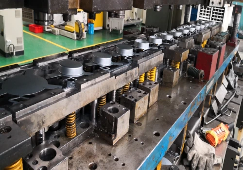
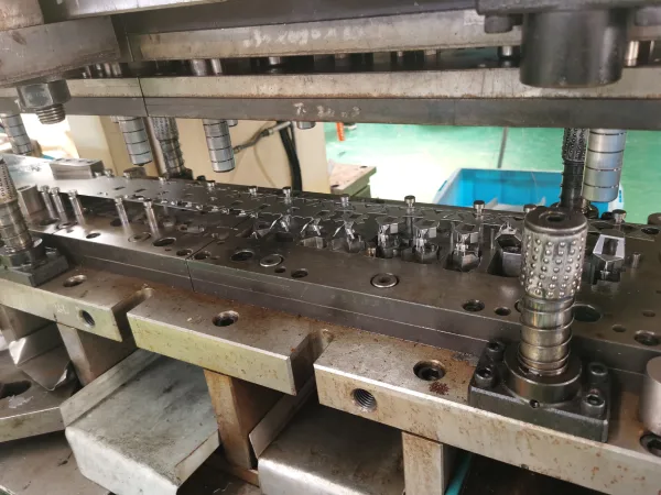

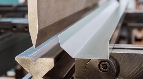
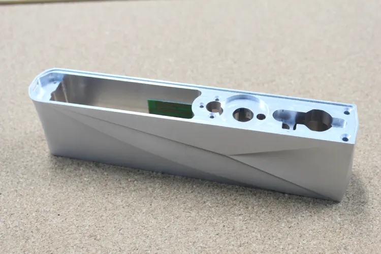
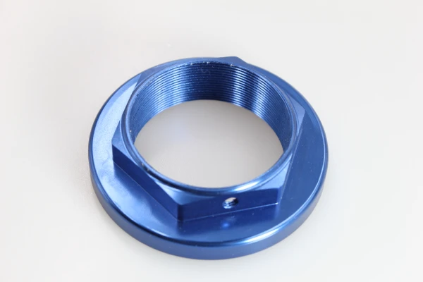
Progressive die stamping is a high-speed metal forming process in which strip material fed continuously from a coil passes sequentially through multiple stations within a single die set, with each station performing a distinct processing operation—punching, blanking, bending, coining, or deep drawing—until the finished part is separated from the carrier at the final station. Productivity ranges from 7 to 1,500 parts per minute, with dimensional tolerances of ±0.025 millimeters achievable over millions of cycles.
However, this level of performance depends on one indispensable prerequisite: the precise positioning of the strip at each station. A typical progressive die contains 4 to 30 stations, each designed with reference to the preceding operation.
When the strip advances correctly, the progressive die stamping process delivers consistent output with minimal deviation. However, once misalignment occurs, the consequences trigger a chain reaction—initial positional errors, initially on the micrometer scale, accumulate across stations, often resulting in scrap rates exceeding 15%. In severe cases, this can even cause damage to the progressive stamping die, leading to production stoppages.
This article examines the three primary sources of alignment errors in custom progressive die stamping—pitch errors, pilot pin calibration failures, and improper feeder release timing—analyzes the mechanism by which errors accumulate across stations, and proposes corresponding corrective strategies based on fundamental die debugging principles and diagnostic procedures.
Definition of Misalignment in Progressive Die Stamping
In a high-speed progressive die stamping environment, misalignment refers to any deviation between the actual position of a metal strip and its designed position as it passes through the various stations within the die. A typical progressive die contains 4 to 30 stations, each performing a specific operation such as punching, blanking, bending, coining, or deep drawing. These stations are arranged at precise intervals (i.e., pitch) that match the feed distance of the strip with each cycle.
The accuracy of the entire system relies on a core principle: while the coil feeder and transport system move the strip from one station to the next, their function is merely to position the workpiece close to the target location so that the die’s positioning mechanisms (primarily pilot pins) can perform the final micrometer-level alignment.
Pilot pins correct the minute errors caused by each feed by entering pre-punched alignment holes in the strip. When this positioning process fails—whether due to pitch error, pilot pin calibration deviation, or improper timing between feeding and pilot pin release—misalignment occurs.
The consequences are cumulative: a 0.1-millimeter positioning error at one station can be amplified to 0.3 to 0.5 millimeters by the time it reaches the final station. For demanding applications, the repeatability of modern progressive dies must be maintained at the 5- to 10-micrometer (μm) level; therefore, any deviation beyond this range can lead to dimensional deviations in the stamped parts, accelerated die wear, or even die damage.
In short, misalignment is the “first spark” that disrupts the stability of the progressive die stamping process and is a critical variable that must be controlled at its source.
Main Causes of Misalignment in Progressive Stamping Dies
Misalignment in progressive die stamping primarily stems from pitch errors, guide pin calibration deviations, and improper feed release timing. Although these three sources of failure are independent, they often compound, directly compromising the positioning references and repeatability between stations, and serving as the root causes of subsequent cascading failures.
Pitch Error
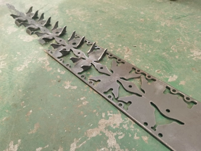
Pitch (also known as feed length) refers to the distance the strip advances during each progressive die stamping cycle. A pitch error occurs when the actual feed length deviates from the designed feed distance. This may be caused by the following factors:
First, incorrect calibration of the feed rollers. The feed rollers clamp the strip and rotate through a specific angle to advance the material by one feed increment. If the rotational distance is incorrectly calibrated, a consistent offset occurs in every cycle.
Second, slippage of the feed rollers. Uneven spring pressure on the left and right sides of the feeder can cause the material to slip, particularly when processing thicker sheets.
Third, coil crown. Camber (i.e., the edges of the coil not being straight) may originate from the feed coil during the slitting process or be caused by the leveler or straightener. Severe camber affects feeding performance and leads to lateral offset.
Fourth, take-up ring tension. If the feed rollers release too early, the weight of the slack ring between the feeder and the coil may pull the strip away from its intended position.
Calibration Errors in Pilot Pins
Pilot pins are the primary positioning mechanism in progressive dies. These cylindrical pins, which have been hardened and ground, are mounted on the upper die and engage with the pre-punched holes in the strip to correct feeding errors before the forming operation is performed. Calibration errors in pilot pins typically manifest in the following three ways:
First, insufficient guide engagement. The effective diameter of the pilot pins must extend beyond the surface of the pressure pad or release pad to correctly position the workpiece before pressure is applied to secure it. If the pilot pins fail to engage fully before the pressure pad clamps the strip, the guide holes will become misaligned—the pilot pins may deform, bend, or even break the holes completely.
Second, incorrect guide clearance. The clearance around the pilot pins is determined by the thickness of the progressive stamping materials, the workpiece dimensions, and the tolerance requirements. Insufficient clearance will cause the workpiece to rise along with the pilot pins; excessive clearance will result in positional drift.
Third, wear or damage to the pilot pins. Pilot pins are subject to wear during the production cycle of custom progressive die stamping. When pilot pins lose their tapered profile or become seized, their positioning accuracy decreases, thereby introducing cumulative errors.
Improper Feed/Pilot Release Timing
Feed release refers to the moment when the feed rollers actively release the strip as the pilot pins begin to enter the strip’s guide holes, allowing the strip to float freely during the subsequent die closure process, with the pilot pins independently completing the final positioning.
If release occurs too early, the strip will experience slight pullback due to the reverse tension from the take-up winch after the rollers open, causing a negative deviation in the longitudinal direction; if release occurs too late, the rollers will still be clamping the strip, and the pilot pins will be subjected to excessive lateral shear forces during the forced alignment process, which can result in elongation of the guide holes in mild cases or breakage of the pilot pins in severe cases.
In the progressive die stamping process, the ideal release window should be set when the tapered guide section (bullet nose) of the pilot pins makes contact with the hole opening but before they enter the straight section; this window typically spans a crankshaft angle range of 5° to 10°. For progressive stamping dies equipped with a lifter, it is also necessary to ensure that the lifter has raised the strip to the feed plane before the rollers can close and clamp it again; otherwise, the strip will shift from its initial position as it falls back, causing a deviation in the feed length for the next cycle.
Are you looking for reliable & cost-effective
China metal fabrication manufacturer
More than 150,000 OEM metal fabrication products delivered to 5,000+ global buyers.
And benefit from it!
Cascading Failure Mechanisms in the Progressive Die Stamping Process—How Errors Accumulate
The most insidious aspect of misalignment in progressive stamping dies lies in its cumulative nature. Positioning errors introduced in early stations do not exist in isolation but instead accumulate continuously throughout subsequent operations.
Cumulative Deviation Among Stations
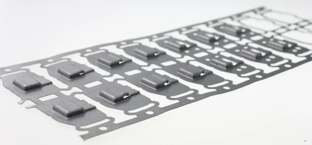
In custom progressive die stamping, the nature of cumulative deviation lies in the fact that the positioning references for subsequent stations are derived from features already machined at the previous station, rather than from theoretical absolute coordinates.
A typical progressive die contains 4 to 30 stations. The positioning error at the Nth station does not occur in isolation but is the sum of all positional offsets introduced at stations 1 through N-1. According to error propagation theory, the total deviation is approximately equal to the algebraic sum of the deviations at each station.
If a pitch drift of 0.02 mm occurs at a given station and is propagated through five subsequent stations, the cumulative deviation at the final bending station may exceed 0.07 mm—while aerospace or automotive chassis parts typically require critical dimensional tolerances to fall within ±0.05 mm.
This nonlinear superposition not only causes the final punching and forming features to deviate from the theoretical centerline but also alters the relative phase between stations, causing interference between the lateral movement of the slide and the timing of strip feeding, which results in the positional relationship between the side punch holes and the alignment holes exceeding specifications.
To control such errors, correction stations (restrike stations) must be planned during the design phase of the progressive die stamping process. By adopting an unconstrained positioning strategy to reset the reference, the transmission path of deviations from preceding stations to subsequent stations is severed.
Secondary Failures
The direct consequence of accumulated deviations is dimensional out-of-tolerance in the progressive die stamping part, while secondary failures refer to indirect damage sustained by the die itself and the process system.
When pilot pins are continuously subjected to lateral correction forces exceeding their design tolerances, the inner walls of the guide holes may experience one-sided extrusion deformation or even tearing. The resulting increase in hole diameter further weakens the positioning constraint stiffness of subsequent stations, creating a positive feedback loop of “increased deviation → weakened positioning → further increased deviation.”
At the same time, due to the misalignment of the strip position at the bending station, the actual contact area between the bending punch and the die cutting edge deviates from the theoretical point of application. This uneven load distribution can cause localized spalling or premature wear of the die inserts, potentially causing the service life of the progressive die to plummet from the design expectation of 5,000,000 strokes to less than 1,000,000 strokes.
More serious secondary failures involve the structural integrity of the progressive stamping die: if positional misalignment causes the guide holes in the stripper plate to be misaligned with the punch center, the lateral bending moment generated during die closure may damage the guide components and even compromise the precision of the press slide.
In the production of custom progressive die stamping, secondary failures caused by misalignment are often more challenging to address than an increase in scrap rates, as the root causes are hidden, troubleshooting is time-consuming, and the entire die set often must be taken offline for repair.
The best way to prevent such failures is to monitor the cutting force curves at each station using sensors during the debugging phase and establish a force-displacement baseline. This provides an early warning as soon as any deviation in the curve is detected, allowing misalignment to be nipped in the bud.
Correction Strategies and Preventive Measures for Alignment Deviations in Progressive Die Stamping
To address misalignment issues in progressive die stamping, correction strategies must focus on four key areas: die alignment, release timing calibration, pilot pin maintenance, and systematic diagnostics. This approach breaks the chain of error propagation and restores consistency in the positioning references between workstations.

Establishing Correct Progressive Die Alignment
Progressive stamping die alignment is a fundamental process for eliminating systematic misalignment. Its objective is to maintain strict parallelism between the die centerline and the feed direction, while ensuring that the feed plane is coplanar with the die base.
In practice, by installing precision key blocks between the die base plate and the press worktable, and using a dial indicator to calibrate both sides of the die, parallelism errors can be controlled within 0.02 mm/m. Matching the feed line height is equally critical—if the feed machine’s exit plane is more than 0.05 mm higher or lower than the die’s feed inlet plane, the strip will be subjected to additional bending stress before entering the first station, altering the direction of force on the pilot pins.
The squareness of the press ram relative to the worktable must also be verified periodically; typically, the deviation is required to be no more than 0.03 mm within a 300 mm stroke range.
It is recommended to perform a quick alignment verification before each batch of custom progressive die stamping production. Manually feed a standard setup strip to confirm the concentricity of each station’s guide holes with the punch center before starting automated production.
Setting Pilot Release Timing Correctly
The standard setting principle is as follows: when the crankshaft rotates to the point where the tip of the pilot pins’ tapered guide section (bullet nose) just makes contact with the upper edge of the strip guide hole, the feed rollers must immediately release (open). This moment typically corresponds to the 180° to 195° range of the press stroke angle, depending on the progressive die’s closing height and the length of the guide pins.
If release occurs too early, the strip will experience a negative deviation in the longitudinal direction due to the pullback caused by the take-up tension; if release occurs too late, a “tug-of-war” effect will develop between the feed rollers and the pilot pins, which at best will cause unilateral squeezing deformation of the guide hole rim, and at worst will result in the pilot pins bending or breaking.
Precise timing requires the use of a cam switch or angle encoder in conjunction with an oscilloscope to capture electrical signals and adjust the installation angle of the release cam, ensuring that the release action is strictly synchronized with the physical process of the pilot pins entering the strip. After debugging is complete, the machine must be run continuously for 10 strokes at a low speed (e.g., 20 SPM) to verify the stability of the timing by comparing changes in the concentricity of the alignment holes at each station.
Design and Maintenance of Pilot Pins in Progressive Dies
The design parameters of pilot pins directly determine their alignment capability and service life. The taper angle of the conical guide section (bullet nose) is typically set between 15° and 30°. A smaller angle provides a gentler alignment force curve, suitable for thin materials (t ≤ 1.0 mm) or high-precision progressive die stamping applications; a larger angle is suitable for thick materials or scenarios requiring greater alignment tolerance.
The diameter of the straight section of the pilot pins should be 0.005–0.015 mm smaller than the nominal diameter of the alignment hole to ensure positioning rigidity while preventing interference jamming.
In terms of materials, powdered high-speed steel (such as ASP2053) or cemented carbide (such as YG6X) are the preferred choices due to their wear resistance and flexural strength; a TiN or TiCN coating may be applied to the surface to extend service life.
For maintenance, it is recommended to inspect the pilot pins under a microscope after every 50,000 progressive stamping strokes, focusing on the conical surface for scratches, buildup, or microcracks; the diameter of the straight section should be measured with a pneumatic gauge every 200,000 strokes, and replacement is required when wear exceeds 0.01 mm of the original diameter. Note that pilot pins in a progressive die should be replaced in pairs to avoid introducing asymmetric alignment forces caused by mixing new and old pins.
Diagnostic Process for Misalignment Issues in High-Speed Progressive Die Stamping
When the scrap rate rises abnormally during custom progressive die stamping production, a systematic diagnostic process can minimize downtime. The recommended troubleshooting sequence is as follows:
Step 1: Inspect the properties of the progressive stamping materials—verify that the strip width tolerance is within ±0.1 mm and check for burrs or waviness (camber) along the edges. These factors are independent of the die but directly affect feed stability.
Step 2: Verify the pilot pin release timing—operate the press slowly in inch mode and observe whether the feed rollers open synchronously when the tips of the pilot pins contact the guide holes; if necessary, use a stroboscope to observe the timing consistency during dynamic operation.
Step 3: Troubleshoot physical obstructions—check for scrap material (slug pulling) between the stripper plate and the strip, verify that the lubricant is not too viscous, causing the strip to stick, and ensure that the lifters fully reset during the return stroke.
Step 4: If no abnormalities are found in the first three steps, remove the progressive die from the press and place it on a coordinate measuring machine (CMM) to remeasure the actual center distances between the cavities of each station. Compare these measurements with the design drawings to verify whether prolonged impact has caused plastic deformation in the die structure. Following this step-by-step troubleshooting process can prevent the introduction of new variables resulting from blindly adjusting the progressive die stamping process parameters.
Conclusion
The misalignment issues in progressive die stamping do not stem from a single source of failure, but rather represent a cumulative process of systemic deviations that are amplified step by step through the interaction of pitch errors, pilot pin calibration deviations, and improper feed release sequencing.
Based on engineering practice in custom progressive die stamping, pitch errors determine the magnitude of reference drift during each feed; pilot pin calibration deviations compromise the consistency of the positioning reference; and improper release timing causes the first two factors to couple dynamically, ultimately manifesting as unacceptable dimensional deviations and rising scrap rates at the final station.
What warrants the greatest caution is not the misalignment itself, but the neglect of early, subtle deviation signals. When a 0.02 mm deviation in the concentricity of a guide hole occurs at a single station, if not addressed promptly, it can easily accumulate to a deviation of over 0.08 mm after passing through five to eight stations—a magnitude sufficient to cause critical functional dimensions of a progressive die stamping part to exceed the ±0.05 mm tolerance band, which in the automotive or electronics industries means the entire batch must be scrapped.
Therefore, the fundamental solution lies in systematic troubleshooting: starting with verifying that the feed line height is coplanar with the die base, then calibrating the release phase of the pilot pins’ tapered surfaces as they enter the guide holes, and finally identifying microscopic anomalies by comparing the baseline data of the punching force curves across each station.
Investment in progressive die debugging and maintenance typically accounts for less than 5% of a project’s total cost, yet it directly determines over 95% of mass production quality stability. For progressive die stamping manufacturers, shifting misalignment prevention from “reactive die repair” to “proactive calibration” is the key path to reducing overall manufacturing costs and improving batch consistency.
For technical parameter inquiries, customized project solutions, or OEM partnership consultations, please contact Supro immediately. Our professional engineering team is ready to provide you with a tailored application solution at any time.