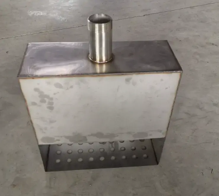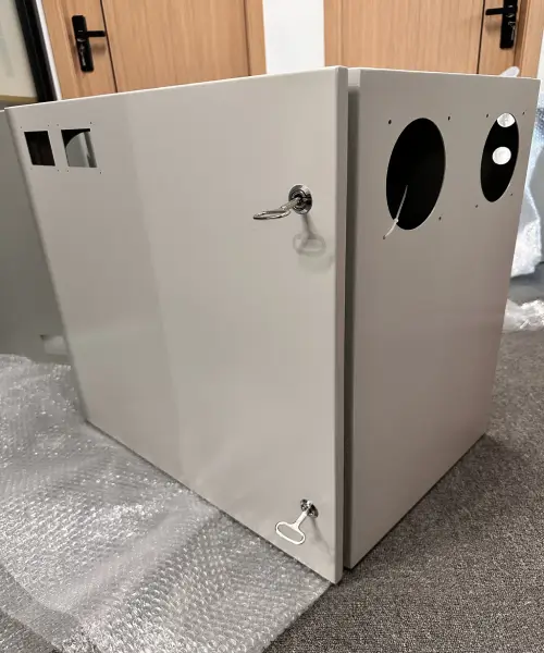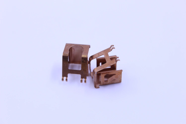
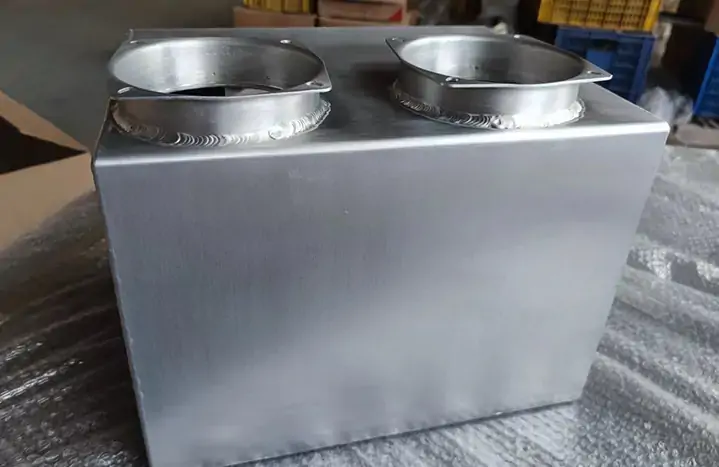

The service life of metal water tanks is often determined not by corrosion or pressure vessel failure, but by fatigue cracks at rigid support connections. High-frequency vibrations caused by pumps and cyclic thermal expansion generate repeated stresses that concentrate at weld roots and areas of sudden cross-sectional change.
In a documented case involving a water storage tank installation, cracks up to 4 millimeters deep were discovered in the welded mounting brackets after only three years of use. Metallographic examination traced the failure mechanism to strain-induced corrosion cracking, caused by the welded brackets acting as local restraints that impeded the natural deformation of the relatively thin and highly elastic metal water tank walls. This local constraint caused stress concentrations in the joint area to exceed the strain tolerance of the protective coating, leading to corrosion propagation into the base metal and the formation of deeper cracks.
Addressing this failure mode in metal water storage tanks requires a two-pronged approach: decoupling vibration transmission at pipe joints using flexible expansion joints, and redistributing load-bearing forces to the support base using stress-dissipating base plates. The following sections will explore these engineering countermeasures and their application in the manufacturing of metal water tanks.
Understanding Fatigue Cracking at the Support Points of Metal Water Tanks
Fatigue failure in the support structures of custom metal water tanks is essentially a high-cycle phenomenon driven by repeated stress amplitudes below the material’s static yield strength. Unlike a single overload event, fatigue accumulates gradually through three stages: crack initiation, propagation, and ultimate fracture.
In metal water storage tank applications, there are two primary sources of cyclic loading. High-frequency vibrations caused by pumps are transmitted through rigidly connected supports, generating localized stress reversals at the connection points. At the same time, temperature differences during operation—that is, the difference between the liquid temperature and the ambient temperature—cause periodic thermal expansion and contraction. When rigid support structures restrict the material’s natural dimensional changes, constraint stresses are generated; these stresses act repeatedly during each thermal cycle, leading to the accumulation of fatigue stresses in the metal water tank shell and supporting components.
Critical crack initiation locations are typically found at weld roots and areas of sudden cross-sectional changes, where geometric discontinuities cause local stress concentrations to be significantly higher than nominal values. In a documented case involving the installation of a water tank, welded supports acting as local clamps prevented the relatively thin tank walls from undergoing elastic deformation, causing strain to concentrate in the joint area and triggering strain-induced crack corrosion, which propagated inward to a depth of 4 millimeters within three years. Understanding these mechanisms is a prerequisite for effectively mitigating fatigue in the design and manufacture of custom metal water tanks.
Stress Concentration Mechanisms in Metal Water Tank Bracket Design
Stress concentration at the joints of metal water tank brackets stems from three interrelated factors: the constraining effect of rigid connections on the shell’s flexibility, the notch sensitivity of the weld root geometry, and the gradual accumulation of damage under cyclic loading. These factors directly determine the initiation location of fatigue.
The Role of Rigid Connections in Transmitting Dynamic Loads to the Metal Water Tank Wall
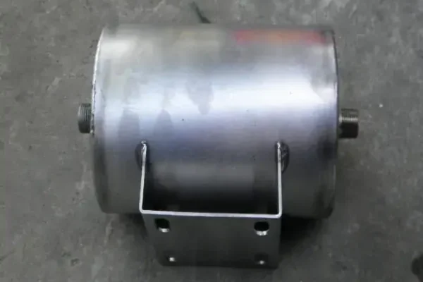
Stress concentration in the design of metal water storage tank supports stems from a fundamental mismatch between the assumption of rigid connections and the actual flexibility of thin-walled tank shells. When vertical loads are transmitted through discrete support brackets welded to the cylindrical tank shell, the orientation of the line of action of the support reaction force relative to the bracket centerline has a decisive influence on the resulting elastic shell stresses.
Rigid connections effectively act as local clamps, preventing the natural deformation of the metal water tank walls and forcing the tank shell to withstand dynamic loads through local bending and redistribution of membrane stresses, rather than through a global elastic response. This constraint causes the stresses at the connection interface to be significantly higher than the nominal values calculated based solely on static loads.
How Weld Geometry Affects the Fatigue Life of Joints
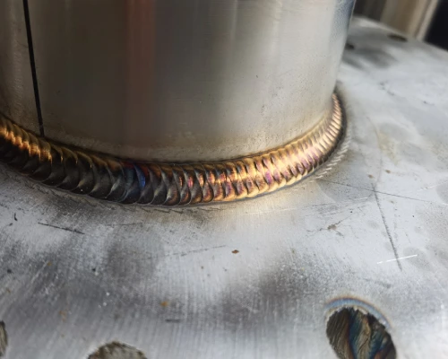
Due to high stress concentrations at the weld toe, weld geometry has a critical impact on the fatigue life of welded joints. The stress concentration factor (SCF)—the ratio of peak local stress to nominal stress—is primarily determined by the local weld toe radius and the groove angle.
Compared to welds with smooth transitions, sharp weld roots with extremely small radii produce significantly higher SCF values, thereby effectively narrowing the permissible range of cyclic stresses for a given fatigue life. In brackets joined by fillet welds, fatigue cracks typically originate at the weld root near the end of the bracket, where geometric discontinuities create a notch effect that amplifies the applied stresses.
Cyclic Loading Patterns and the Cumulative Damage Process
Under cyclic loading—whether caused by pump-induced vibrations or thermal cycling—the cumulative damage process progresses through several distinct stages. In localized areas of stress or strain concentration, cyclic loading leads to the gradual accumulation of local plastic deformation, thereby initiating microscopic fatigue cracks. Subsequently, these cracks propagate under alternating stress, gradually spreading throughout the cross-section.
This process is gradual: each load cycle causes a small increment of damage, and failure occurs when the cumulative damage reaches a critical threshold. For supports in metal water storage tanks subjected to high-cycle, low-amplitude loads, crack initiation typically accounts for the majority of the service life; however, once the crack reaches a critical depth, its propagation rate accelerates sharply. Understanding these mechanisms is critical for designing the support geometry and weld profiles, which helps minimize stress concentrations and improve fatigue resistance in custom metal water tank applications.
Only 4 steps
online custom metal fabrication parts
Contact our experts team and experience the efficiency and economic benefits of digital metal fabrication services.
Upload Design Files
STL , STEP (.stp), IGES (.igs), (.ZIP), or PDF.
Also be a sample or an idea
Quote & Design Analysis
Instant factory quotes and DfM reports, the most reasonable solution.
Manufacturing Begins
Digital processes can initiate order tasks within 24 hours.
On-Time Delivery
Keeping delivery promises, approved by 3000+ Global Company buyers.
Solutions for Mitigating Fatigue in Metal Water Tank Supports
Fatigue mitigation for metal water tank support systems primarily revolves around three complementary strategies: isolating dynamic loads at pipe interfaces, distributing support reaction forces over a larger bearing area, and optimizing weld transition radii to reduce local stress concentration factors.
Flexible Expansion Joints at Metal Water Tank Pipe Connections—Isolating Vibration Transmission
At the connection between rigid piping and the metal water tank, vibrations generated by the pump are transmitted directly through the rigid pipe connection, imposing cyclic stresses on the tank shell at the connection point.
Installing flexible expansion joints (typically multi-layer metal bellows assemblies) between the piping system and the metal water storage tank connections can sever this mechanical transmission path. The bellows can accommodate axial, lateral, and angular displacements while absorbing vibration energy that would otherwise be concentrated at the support welds.
For custom metal water tank applications requiring continuous pump operation, expansion joints effectively transfer flexibility from the rigid support structure to the connection itself, thereby reducing the amplitude of cyclic stress transmitted to the tank shell.
Proper selection of bellows material, number of layers, and pressure rating ensures that the expansion joint maintains its fatigue resistance throughout its expected service life, while providing the necessary displacement capacity without imposing constraint loads on the metal water tank walls.
Stress Distribution Base Plate for Load-Bearing Supports of Metal Water Tanks—Cushioning Dynamic Impacts
When metal water storage tanks are placed on discrete support brackets, concentrated support reactions are transmitted through a small contact area, resulting in high local stresses at the connection between the brackets and the tank shell. The stress-distribution base plate—that is, an oversized steel plate welded or bolted beneath the load-bearing point—distributes the support load over a larger area of the tank shell, thereby reducing the peak stress intensity at any single point. This approach addresses the fundamental mechanism behind fatigue cracking: localized stresses exceeding the endurance limit of the tank material.
By increasing the bearing area, the base plate reduces the nominal stress level at the connection, thereby effectively increasing the margin between the applied stress and the material’s fatigue threshold. In unanchored metal water tank structures, where the base plate may warp during operation, a properly designed base plate can also distribute the resulting membrane stress more evenly, thereby reducing the risk of low-cycle fatigue at the connection between the tank shell and the base plate.
The thickness and planar dimensions of the base plate must be engineered based on the wall thickness of the metal water tank to avoid simply transferring stress concentrations to the edges of the base plate.
Geometric Optimization of the Weld Transition Zone—Increasing the Radius to Reduce Stress Concentration
The fatigue life of welded joints in metal water tank support assemblies primarily depends on stress concentration at the weld root. Immediately after welding, the radius at the weld root is typically about 0.25 millimeters, which creates a sharp geometric discontinuity, often resulting in a local stress increase exceeding 10 times the nominal stress. Increasing this radius through post-weld grinding or TIG trimming can significantly reduce the stress concentration factor (SCF).
Finite element analysis indicates that the radius of curvature has a more significant impact on the SCF than the weld side angle; therefore, the root radius becomes the primary geometric parameter for improving fatigue performance.
For metal water tank supports subjected to high-cycle loads, grinding the weld root to a radius of 2 millimeters or greater can reduce the effective stress concentration factor by approximately 50% compared to the as-welded condition.
This geometric optimization shifts the fatigue crack initiation location from the sharp notch to an area with lower stress concentration, thereby effectively prolonging the crack initiation stage and delaying crack propagation to the critical depth.
Material Selection and Thickness Considerations for High-Cycle Metal Water Tank Applications
Material selection and tank wall thickness are the fundamental determinants of fatigue resistance in metal water tank manufacturing. Provided that weld details are properly designed to minimize stress concentration, high-strength steel typically exhibits superior fatigue performance under cyclic loading.
However, material strength alone does not guarantee fatigue durability; the wall thickness of the metal water tank at support connections directly affects local stiffness, which in turn influences the stress distribution when loads are applied. Thicker walls can reduce the membrane and bending stresses caused by support reactions, thereby lowering the nominal stress level when applying the SCF. For elevated-temperature service, ASME Boiler and Pressure Vessel Code Section VIII, Division 2 provides guidance on derating yield strength and establishing allowable cyclic stress ranges.
In high-cycle applications where custom metal water tanks frequently undergo fill-and-drain cycles, designers must specify a wall thickness that ensures peak local stresses—taking into account stress concentration factors at the weld root and stress amplification effects caused by rigid connections—remain below the material’s endurance limit.
Are you looking for reliable & cost-effective
China Sheet Metal Fabricators
More than 150,000 OEM metal fabrication products delivered to 5,000+ global buyers.
And benefit from it!
Process Considerations for Fatigue-Resistant Metal Water Tank Manufacturing
The manufacturing process directly affects the fatigue performance of custom metal water tanks. The precision of cutting, bending, and welding determines the final geometry, residual stress distribution, and notch severity at critical joints. Surface treatment further influences their resistance to corrosion fatigue. Next, we will examine each stage of metal water tank manufacturing in turn.
Precise Control of Bracket Geometry Through Precision Laser Cutting and Bending
The geometry of metal water tank brackets directly affects the stress distribution at the joint interfaces. Laser cutting technology can produce complex contours with positioning accuracy of ±0.10 mm for thin sheets and ±0.15–0.25 mm for thicker sections, thereby ensuring that the bracket contours conform to the design intent and avoiding unintended notches or deviations that could become stress concentration points.
However, the laser-cut edges themselves produce characteristic structures—recrystallized material in the form of burrs and spatter—which can act as crack initiation points under cyclic loading.
Therefore, for brackets supporting metal water tanks subjected to high-cycle vibration, post-cutting edge treatment is just as critical as the cutting accuracy itself. Subsequent CNC bending (with an angular accuracy of ±0.2°) ensures that the formed brackets maintain the intended load path, preventing unintended eccentricity from exacerbating stress at the welded joints. The combination of strict dimensional control and edge quality management directly determines the fatigue performance of custom metal water tanks.
Welding Techniques to Minimize Residual Stresses and Defects in the Heat-Affected Zone
Welding introduces thermal cycles, resulting in residual stresses and microstructural changes in the heat-affected zone (HAZ)—both of which reduce the fatigue resistance of the support structure for custom metal water tanks.
Advanced simulation techniques, such as finite element analysis, can accurately predict temperature distributions, residual stresses, and deformations prior to actual welding, enabling designers to identify high-stress areas and implement corrective measures before the metal water tank is manufactured.
The heat-affected zone (HAZ) warrants particular attention: localized heating and rapid cooling can lead to grain coarsening and hardness gradients, thereby reducing the material’s ability to withstand cyclic strain. Post-weld stress relief through controlled heating or vibration treatment can reduce residual tensile stresses that would otherwise superimpose on the applied cyclic loads.
For critical bracket connections, welding sequence planning and fixture design can minimize distortion and locking stresses. These proactive measures ensure that the fatigue performance of the welded components approaches that of the base material, rather than introducing weak points that could compromise the service life of the metal water tank.
Quality Inspection Procedures—Dimensional Tolerances and Weld Integrity Verification
For the manufacturing of fatigue-critical metal water tanks, verification of dimensions and weld quality is non-negotiable. ISO 5817:2014 specifies three quality classes—B, C, and D—for defects in fusion-welded joints, with Class B representing the highest requirements and typically applying to critical welds in special structural categories.
For support brackets of metal water tanks subjected to cyclic loads, specifying Grade B ensures that defects such as porosity, undercut, and lack of fusion are controlled within the strictest limits.
In accordance with ISO 17635:2016, appropriate non-destructive testing (NDT) methods are selected based on the material, weld thickness, and quality requirements. Visual testing (VT) and magnetic particle testing (MT) or penetrant testing (PT) are used to detect surface defects, while radiographic testing (RT) or ultrasonic testing (UT) are used to verify internal integrity.
By cross-checking dimensions against the CAD model, it can be confirmed that the support bracket contours and hole positions of the metal water tank are within the specified tolerances, thereby ensuring that the manufactured components conform to the engineering design—a prerequisite for the validity of stress analysis under on-site operating conditions.
Surface Treatment and Its Role in Preventing Corrosion Fatigue
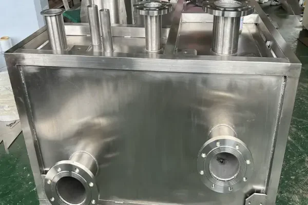
Corrosion and fatigue have a synergistic effect: in the presence of corrosive media, cyclic loading accelerates crack propagation, while pits formed by surface corrosion serve as crack initiation sites. For metal water storage tanks, the inner surfaces are particularly susceptible to corrosion. Eliminating crevices—such as those associated with semi-penetrating welds—removes areas where chlorides may accumulate, thereby preventing the formation of localized acidic environments that accelerate corrosion.
Post-weld cleaning and chemical passivation can restore the chromium oxide layer on the surface of stainless steel, thereby restoring the corrosion resistance compromised by welding heat. For carbon steel water tanks, epoxy coatings provide a barrier against corrosion on the water-facing side. The corrosion rate is influenced by local chromium concentration, water chemistry (particularly chloride content), surface characteristics that lead to localized acidification, and the amplitude of cyclic loads.
When manufacturing custom metal water tanks, selecting pitting-resistant steel grades such as 316L provides an additional safety margin. These surface protection measures ensure that the fatigue life determined by the mechanical design is not prematurely shortened by corrosion-assisted crack initiation and propagation.
Looking for a reliable custom sheet metal fabrication companies?
Talk To Supro MFG Expert Team
Contact us for competitive ex-factory prices,
and a full range of technical support services.
Conclusion
Fatigue cracking at the support joints of metal water tanks is not caused by a single factor, but rather results from the combined effects of cyclic loading, geometric discontinuities, and manufacturing quality.
For custom metal water tanks, mitigating this failure mode requires a systematic approach: decoupling vibrations at pipe interfaces, redistributing support loads through stress-relief base plates, optimizing weld toe geometry to reduce stress concentration factors, and selecting materials and wall thicknesses suitable for cyclic service conditions. However, these engineering measures can only realize their full potential through precision laser cutting, controlled welding sequences, rigorous non-destructive testing (NDT) verification, and appropriate surface protection measures.
A well-designed custom metal water tank—one that comprehensively considers the above factors from design through final inspection—can deliver a longer service life and predictable reliability.
Supro is a professional custom metal water tank manufacturer. Leveraging advanced equipment, extensive manufacturing experience, and a professional engineering team, we provide perfect metal fabrication solutions to more than 3,000 companies worldwide and offer genuine manufacturer quotes.
If you require technical consultation, design solutions, or product specifications, please feel free to contact our engineering team at any time.