

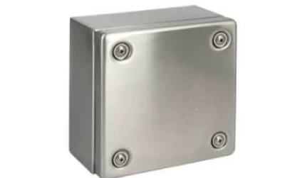


Moving metal stamping parts from the CAD screen to full-scale production requires not only a functional design intent but also strict adherence to Design for Manufacturability (DFM) principles.
Ignoring the basic rules of metal stamping will directly result in costly die modifications, extended lead times, and higher unit costs. Defects on the shop floor—such as microcracks, severe springback, or excessive die wear—rarely stem from operator error. Instead, these defects are typically “designed” into the part during the drafting phase due to misjudgments regarding material yield strength, tonnage limits, and die clearances.
This article bridges the gap between theoretical engineering and shop-floor reality. By mastering key precision metal stamping tolerances, calculating precise bending radii, and making strategic material selections, most production bottlenecks can be eliminated before any die steel is cut.
At Supro MFG, we regularly review technical drawings, and it has been proven that optimized custom metal stamping designs ensure lower die investment and enable stable, high-yield production.
Critical Metal Stamping Tolerances for Precision Parts
Setting overly tight tolerances in sheet metal stamping projects can significantly increase die costs and die maintenance cycles, yet may not necessarily improve part functionality. Defining realistic dimensional limits based on ISO standard guidelines ensures repeatability of assembly fits and enables cost-effective production.
Standard Tolerances vs. Tight Tolerances
Although modern metal stamping presses can achieve extremely tight tolerances as low as ±0.002 inches (±0.05 mm), doing so unnecessarily drives up the cost per unit. For most functional brackets and housings, standard tolerances of ±0.010 inches, in accordance with the ISO 2768-m standard, are entirely sufficient.
Pursuing high precision when it is not strictly necessary will necessitate the use of high-end carbide die components and require frequent die maintenance to address tool wear.
As an experienced metal stamping manufacturer, we recommend that procurement managers work with the engineering team to review drawings and relax tolerance requirements for non-critical dimensions. This proactive Design for Manufacturability (DFM) strategy can significantly reduce initial die investment, shorten lead times, and ensure a more stable precision metal stamping production process—all without compromising the structural integrity or performance of the final assembly.
Blanking and Punching Clearances
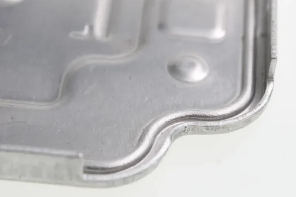
In any metal stamping process, achieving clean edge profiles depends entirely on the optimization of the clearance between the punch and the die. This clearance is typically calculated as a percentage of the material thickness (T) and, for cold-rolled steel, generally ranges from 8% to 12%. If the clearance is too small, it increases the required punching force, leading to excessive die wear and secondary shearing. Conversely, excessive clearance leads to significant burr formation and creates an overly large fracture zone at the cut edge (die fracture).
For high-volume precision metal stamping projects, the correct design of this clearance is non-negotiable. It determines the ratio of the polished area to the torn area, directly affecting whether the part requires a secondary deburring process—which ultimately impacts the final cost to the procurement department.
Minimum Hole Diameter and Edge Distance
In the metal stamping process, one of the most common causes of die failure is specifying a hole diameter that is too small or positioning the hole too close to the workpiece edge.
To prevent punch breakage, the golden rule is that the hole diameter must be strictly greater than the material thickness (for low-carbon steel, D ≥ 1.2T). Similarly, the hole edge clearance (i.e., the minimum distance from the hole edge to the outer edge of the workpiece) should be at least 1.5 times the material thickness (1.5T). Failure to adhere to these strict parameters can result in localized material deformation, edge bulging, and premature punch breakage under the intense impact of the metal stamping process.
By reviewing your CAD files against these fundamental rules, we will help purchasing managers avoid costly design revisions and ensure a smooth, uninterrupted manufacturing process.
Only 4 steps
online custom metal fabrication parts
Contact our experts team and experience the efficiency and economic benefits of digital metal fabrication services.
Upload Design Files
STL , STEP (.stp), IGES (.igs), (.ZIP), or PDF.
Also be a sample or an idea
Quote & Design Analysis
Instant factory quotes and DfM reports, the most reasonable solution.
Manufacturing Begins
Digital processes can initiate order tasks within 24 hours.
On-Time Delivery
Keeping delivery promises, approved by 3000+ Global Company buyers.
Understanding Bending Radii in the Metal Stamping Process
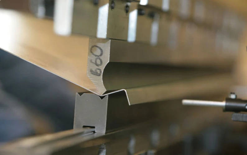
Errors in bending radius calculations can compromise structural integrity and lead to severe microcracks at the outer radius. In any custom metal stamping project, specifying the correct inner bending radius based on the material’s yield strength not only avoids costly die modifications but also ensures defect-free, repeatable high-volume production.
Minimum Bending Radius Guidelines for Different Materials
Each alloy reacts differently to bending stress. If the specified inner radius is too small for the selected material, the outer fibers will be stretched beyond their ultimate tensile strength, triggering microcracks and resulting in scrap parts. In standard metal stamping production, soft aluminum alloys such as 5052 can typically achieve a bend radius of 1T (i.e., 1 times the material thickness). However, harder materials, such as 6061-T6 aluminum alloy or 304 stainless steel, require larger bend radii—typically 2T to 3T—to prevent fracture.
At Supro MFG, our DFM analysis cross-references your CAD geometry with the material’s yield strength to ensure a flawless precision metal stamping process and avoid unexpected scrap costs.
Springback Control in the Metal Stamping Process
Springback refers to the inevitable elastic recovery of sheet metal after it is removed from the forming die. The severity of this angular deformation depends largely on the material’s yield strength and the selected bend radius. To achieve precise angles in any custom metal stamping project, die engineers must proactively compensate for this effect through precise bend radii.
For high-strength low-alloy (HSLA) steel or stainless steel, springback is more pronounced than in standard cold-rolled steel. We typically recommend adding local reinforcement structures (such as formed corner ribs or gussets) to lock in the angle. Mastering springback prediction during the precision metal stamping die design phase ensures that parts assemble perfectly on the production line, thereby avoiding costly manual rework or secondary metal stamping calibration operations.
Designing Effective Bending Chamfers
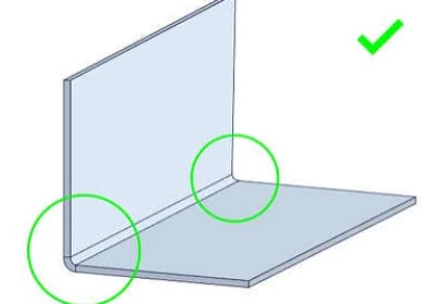
When a flange is bent adjacent to an unbent, flat surface, opposing material stresses at the transition point can cause severe tearing. To isolate these stresses, engineers must incorporate appropriate bend chamfers into the blank layout.
A fundamental rule of robust sheet metal stamping design is that the chamfer width should be at least 1.5 times the material thickness (1.5T). Additionally, the depth of the chamfer cut must exceed the bend radius plus the material thickness (R + T). Failure to properly set these cuts will result in deformation of metal stamping parts and unpredictable die wear.
By strictly adhering to these chamfering standards, our engineers are able to effectively prevent structural fatigue. This ensures that every batch of products delivered to your assembly line maintains high-quality structural integrity.
Are you looking for reliable & cost-effective
China Sheet Metal Fabricators
More than 150,000 OEM metal fabrication products delivered to 5,000+ global buyers.
And benefit from it!
Strategic Material Selection for Metal Stamping
The choice of raw materials largely determines the price of the final product. To successfully implement a precision metal stamping project, engineers must carefully balance ultimate tensile strength against sheet formability. Selecting incompatible alloys will inevitably lead to increased die wear, frequent press downtime, and negate the project’s return on investment.
Comparison of Cold-Rolled and Hot-Rolled Carbon Steel
For structural metal stamping applications requiring thicknesses greater than 0.125 inches (3 mm), hot-rolled steel (HRS/SPHC) can significantly reduce upfront costs. However, the coarse scale remaining on the surface of hot-rolled steel accelerates abrasive wear on dies and requires mechanical sandblasting prior to powder coating. In contrast, cold-rolled steel (CRS/SPCC), which undergoes secondary rolling at room temperature, not only offers extremely precise dimensional tolerances but also features an excellent surface finish, allowing for direct electroplating.
For procurement professionals, the choice of raw material directly determines the budget for secondary processing. If your precision metal stamping project requires strict dimensional accuracy and does not necessitate extensive surface pretreatment, then CRS is well worth the investment, even if it is slightly more expensive.
At Supro MFG, we precisely calculate the cost break-even point to ensure that your material selection optimizes both die life and final unit cost in any sheet metal stamping production.
Stainless Steel Alloys (304, 316, 430)
Since stainless steel is known for its extremely high work-hardening rate, selecting it significantly alters die requirements. Austenitic 304 offers exceptional deep-drawing properties, while 316, with its superior molybdenum-based corrosion resistance, is particularly suitable for the marine and medical device industries. However, these alloys can rapidly degrade the performance of standard die steel in sheet metal stamping applications. To prevent galling, high-quality metal stamping dies must incorporate carbide inserts or advanced PVD coatings.
If the level of chemical corrosion is moderate, switching to ferritic 430 stainless steel can significantly reduce material costs without compromising aesthetic quality. Procurement teams must understand that selecting the precise steel grade can prevent catastrophic die failure. Our engineering team will match you with the alloy that offers the best formability based on your specific environmental requirements.
Aluminum Alloys (5052 and 6061)
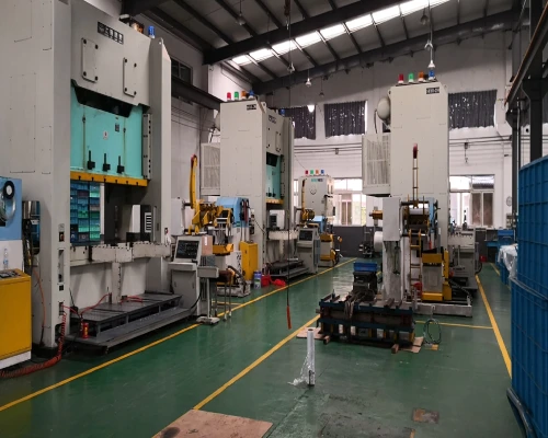
Aluminum is widely favored for its lightweight advantages, but selecting the wrong aging condition can lead to failure in custom metal stamping production. The 5052-H32 alloy is the industry “workhorse,” offering excellent formability and the ability to undergo sharp-angle bending without fracturing. In contrast, while 6061-T6 possesses aerospace-grade structural yield strength, it is extremely brittle under forming stresses.
If you attempt a standard 1T bend on 6061-T6, its outer grain structure will fracture immediately. To successfully machine 6061 material, the metal stamping process must specify a larger bend radius (3T+) or form the part into the softer T4 condition prior to artificial aging treatment.
Confusing these two heat-treated conditions will result in a 100% scrap rate. We rigorously review every aluminum metal stamping drawing to ensure that the selected alloy perfectly meets your structural load requirements while complying with geometric bending limitations.
The Importance of Material Grain Direction in Metal Stamping
A highly technical yet often overlooked factor is the material’s grain direction—that is, the anisotropic flow lines formed during the rolling process at the steel mill. In a reliable custom metal stamping design, the bend line must be perpendicular (or at least transverse) to this grain direction. Bending along the grain direction is like splitting wood and will cause immediate cracking at the outer radius.
This geometric constraint largely determines how blanks are laid out on the coil. Sometimes, optimizing strip layout to maximize material utilization forces the bending direction to be parallel to the grain direction, leading to product failure during actual use.
A professional metal stamping manufacturer prioritizes structural integrity over extracting one more part from the coil. Our DFM (Design for Manufacturability) protocol analyzes grain orientation to ensure that every custom metal stamping part can withstand the rigors of operational fatigue while maintaining optimal coil utilization.
Why choose Supro MFG's Custom Metalworking Services
Provide the most cost-effective cost solution for manufacturing and assembling products, expanding product competitiveness.
a technical team specializing in custom shell manufacturing for more than 30 years.
Advanced Manufacturing Equipment: Industry-leading custom metal enclosure manufacturer with in-house sheet metal, die casting, precision machining workshops, and surface coating workshops.
ISO 9001-2015, PPAP III level, RoHS, NEMA, CE and other certified production standards.
24H*7 online English technical support: The professional English team responds quickly to users’ technical questions online at any time.
help users from product design, prototype, batch manufacturing, surface treatment, assembly and packaging, transportation and a series of value-added services.
With in-house mechanics and chemistry laboratories, it can quickly monitor manufacturing process quality control to ensure the delivery of high-quality products.
Accept to sign NDA documents to ensure that customers’ product information is protected.
Door-to-door delivery in customizable secure packaging after complying with the delivery details agreed with the customer.
Advanced Metal Stamping Features: Flanges, Extrusions, and Embossed Features
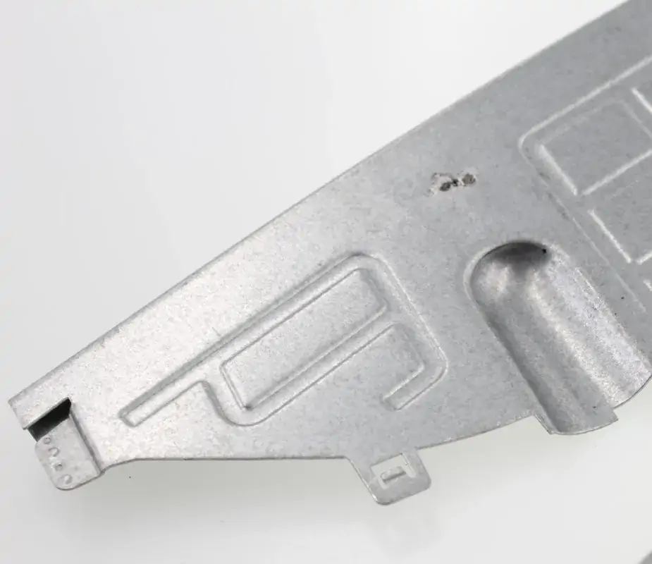
Beyond basic blanking processes, integrating complex 3D geometries—such as extruded threaded holes or embossed features—directly into the metal stamping die eliminates the need for costly secondary machining operations. This strategic part integration not only enhances structural rigidity but also significantly reduces final assembly costs for procurement teams.
Formed Flanges and Countersunk Holes
Integrating formed flanges and countersunk holes directly into the die is a proven method for eliminating secondary hardware. Compared to welding expensive nuts, custom precision metal stamping dies can form hole flanges through extrusion, increasing the material thickness to three times the original, thereby providing ample thread engagement space for tapping.
To achieve a flush assembly, stamped countersunk holes must precisely match the fastener profile—typically 82 degrees for ANSI screws and 90 degrees for metric screws. A key DFM rule in any sheet metal stamping layout is to ensure that the countersink depth preserves at least 50% of the base material integrity to prevent sheet tearing.
By integrating these 3D geometries directly into the progressive metal stamping process, procurement teams can significantly streamline the bill of materials (BOM) and completely eliminate time-consuming and inefficient manual fastener installation processes.
Ribs, Louvers, and Reinforcement Plates
To address rising raw material costs, engineers can reduce sheet metal thickness and restore lost structural stiffness by forming ribs, louvers, and reinforcement plates. Strategically placed stamped ribs increase the moment of inertia of metal stamping parts, significantly improving the stiffness of flat parts without adding actual weight.
Similarly, embossing corner stiffeners into 90-degree bends locks the angle in place, effectively counteracting springback and preventing structural fatigue under severe vibration. For electronic enclosures, louvered ventilation structures can be directly integrated into progressive metal stamping dies, providing critical airflow without the need for secondary processing.
At Supro MFG, we frequently assist purchasing managers in optimizing bracket designs. By applying these advanced precision metal stamping forming techniques, you can achieve yield strengths comparable to those of thicker sheet metal while using lighter, more cost-effective metal blanks.
Looking for a reliable custom sheet metal fabrication companies?
Talk To Supro MFG Expert Team
Contact us for competitive ex-factory prices,
and a full range of technical support services.
Partner with Supro MFG to Optimize Your Metal Stamping Designs
To turn complex CAD models into profitable production runs, a rigorous DFM review must be conducted well before cutting into the die steel. At Supro MFG, our engineering team proactively analyzes your metal stamping drawings to optimize nesting layouts, maximize sheet metal utilization, and adjust critical bend radii to prevent material fractures. By identifying conflicts caused by overly tight tolerances early on, we not only avoid costly die modifications but also significantly shorten your product’s time to market.
Stop paying for over-engineered features. Submit your STEP, IGES, or PDF files to us today, and let our expert metal fabrication team tailor a cost-effective metal stamping solution that precisely meets your assembly requirements.