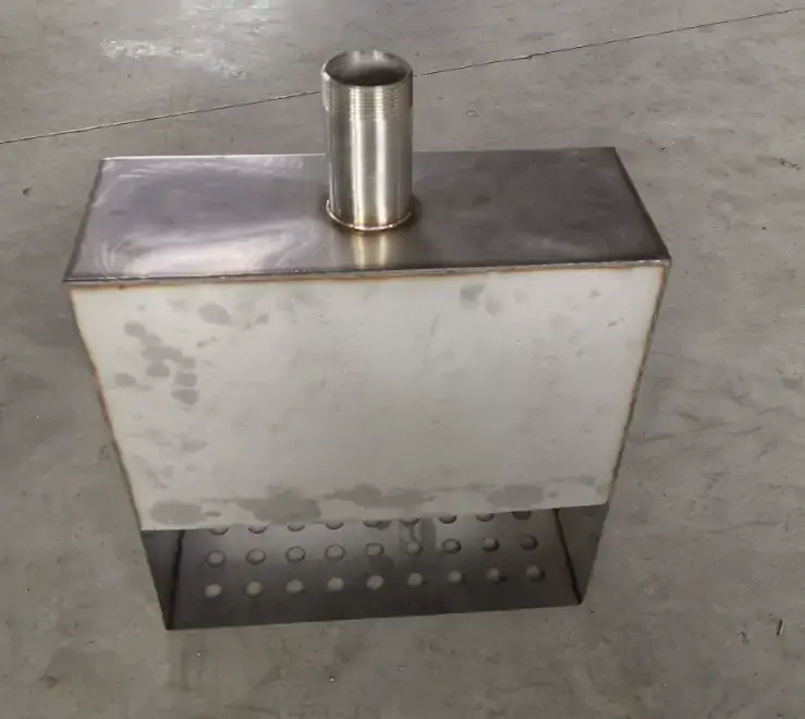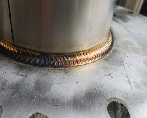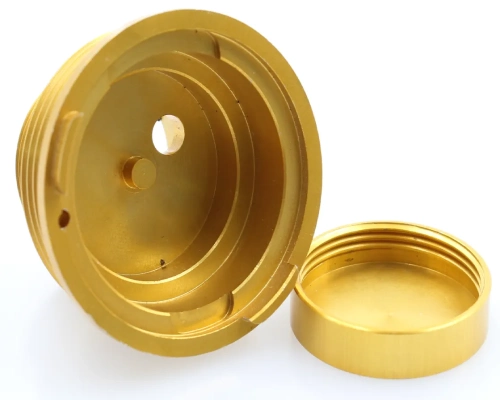

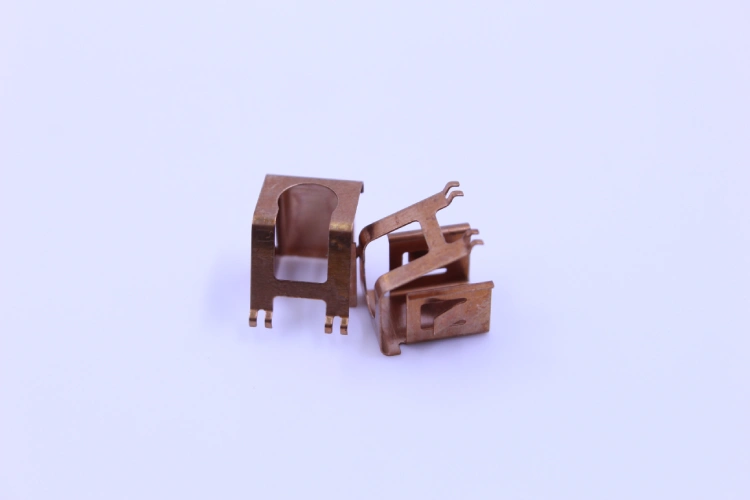
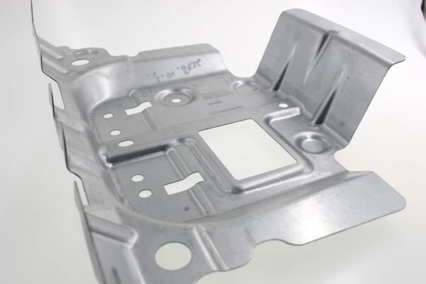

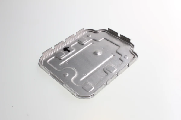
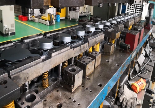
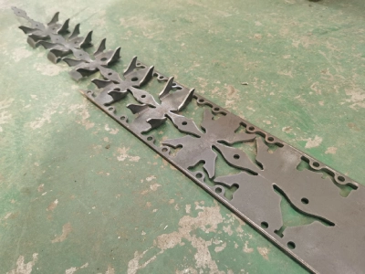
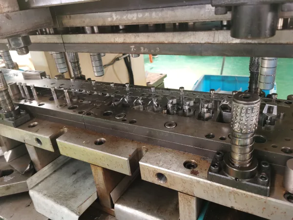

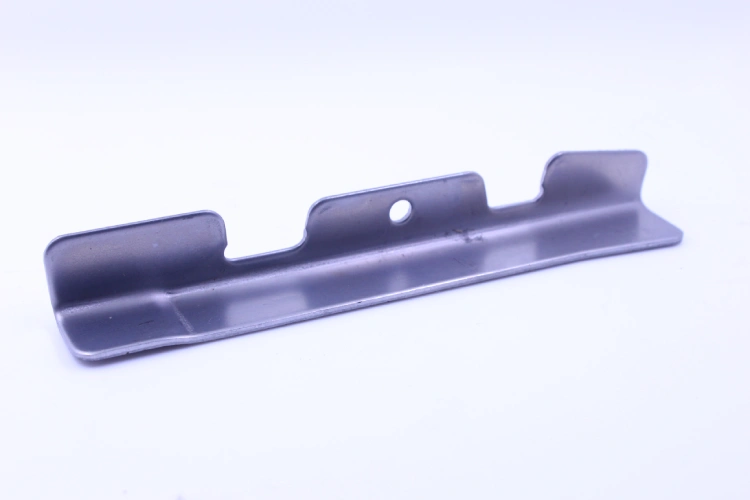
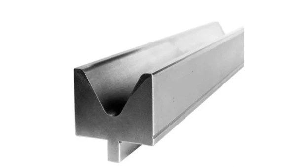
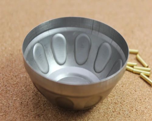
Deep draw stamping is a sheet metal forming process in which a punch applies compressive force to the center of a flat metal blank, generating tensile and compressive stresses as the material is drawn into the die cavity, thereby producing hollow, seamless parts.
When the depth of the formed part exceeds its diameter or width, the process is formally classified as deep drawing. Unlike traditional stamping processes such as cutting, punching, or shallow bending, the deep draw stamping process induces significant radial and circumferential material flow, resulting in parts with uniform wall thickness and structural integrity—a level of quality that cannot be achieved through welding or assembly processes.
Customized deep draw stamping can achieve production rates of 15 to 40 parts per minute on mechanical presses, supporting high-volume manufacturing projects with consistent dimensional accuracy and repeatability. The cold-forming nature of this process preserves the metal’s grain structure and increases tensile strength by 10% to 30% through work hardening, with the specific increase depending on the material and draw depth.
These characteristics make deep draw stamping technology the preferred manufacturing method for producing components such as battery casings, fuel system housings, surgical instrument bodies, and fluid transfer assemblies in the automotive, aerospace, medical, electronics, and home appliance industries.
This guide will explore the process principles, design parameters, material selection criteria, defect prevention strategies, and quality control methods that determine the success of deep draw metal stamping operations—technical considerations that directly impact part cost, lead time, and supply chain reliability.
How the Deep Draw Stamping Process Works
Deep draw stamping follows a series of controlled operational steps. A pre-cut flat metal blank is placed into an open die cavity and secured by a blank-holding device, which applies controlled downward pressure. Subsequently, the punch descends at a controlled speed, pushing the blank into the die cavity and inducing radial material flow from the blank’s edges into the cavity. The relative motion between the punch and the die forces the metal into the die cavity, while the pressure from the blank holder restrains the blank’s periphery.
Key Process Parameters for Deep Draw Stamping
Deep draw metal stamping relies on three interdependent parameters that collectively define the process window. Blank holder force (BHF) controls the flow of material from the flange into the die cavity—insufficient pressure can cause buckling and wrinkling, while excessive pressure restricts radial flow and increases tensile stress at the punch tip, thereby raising the risk of fracture.
Punch speed directly affects formability; slower punch speeds allow sufficient time for the metal to flow into the die. Carbon steel processing typically occurs at speeds of 20–80 mm/s.
Lubrication reduces friction at the interface between the blank and the die; for carbon steel, high-viscosity lubricants with viscosities in the range of 80–120 cSt prevent surface galling and reduce the load requirements on the punch.
A real-time monitoring system using piezoelectric sensors can detect force fluctuations exceeding ±2.5% of the reference value and trigger automatic press adjustments within 50 milliseconds. The interaction among these parameters determines whether the customized deep draw stamping process ultimately produces compliant parts or scrap.
Single-Stage and Multi-Stage Deep Drawing
The distinction between single-stage and multi-stage deep draw stamping depends on the draw ratio—that is, the relationship between the blank diameter and the punch diameter. For most materials, the maximum draw ratio that can be achieved in a single stamping stroke ranges from 1.8 to 2.3. Parts requiring a draw ratio exceeding 3.0 must employ a multi-stage process, with controlled thinning performed at each subsequent stage.
Compared to single-stage deep drawing, two-stage cup-forming deep drawing can reduce the maximum drawing force by up to 24%. Materials that undergo work hardening during the deep draw stamping process (especially high-strength steel and aerospace superalloys) require intermediate annealing between stages to restore ductility and prevent tearing. Multi-stage deep draw stamping gradually distributes strain, thereby reducing peak stress at any single point and enabling geometries that cannot be safely achieved in a single stamping operation.
Cold Forming Characteristics
Deep draw metal stamping is a cold forming process performed at room temperature, in which the metal blank undergoes plastic deformation without external heating. Cold forming preserves the metal’s grain structure and, compared to hot forming, produces parts with higher surface quality and tighter dimensional tolerances.
Cold work hardening occurs during the cold drawing process: as dislocations accumulate within the crystal lattice, the material’s resistance to further deformation increases. This phenomenon increases the tensile strength of the formed part by 10% to 30%, depending on the material and the depth of drawing.
Metals with high ductility and low yield strength—such as low-carbon steel, aluminum alloys, and certain grades of stainless steel—perform best under cold deep draw stamping conditions. Strain hardening behavior is quantified by the n-value (work hardening index), a key mechanical property that determines whether a material can distribute strain uniformly during the forming process.
Deep Draw Stamping vs. Progressive Die Stamping
Understanding the differences between progressive die stamping and the deep draw stamping process is crucial for selecting the appropriate manufacturing process. Progressive die stamping forms parts through multiple stations within a single die, with each station performing a specific operation in sequence. Throughout the entire process, the part remains connected to the carrier strip until it is finally cut off, enabling positional tolerances as tight as 0.001 inches between features.
In contrast, deep draw stamping technology involves drawing the blank into the die cavity through one or more drawing operations to reduce its thickness. This process places greater emphasis on wall thickness uniformity and seamless hollow structures rather than the precision of planar features; therefore, dimensional tolerances for planar features are typically more lenient.
When part depth is the primary design consideration, customized deep draw stamping becomes the preferred choice—geometric shapes such as cylindrical forms, closed ends, and uniform wall thickness often exceed the scope of what flat stamping processes can efficiently handle.
The choice between these two processes depends on the part’s geometry, depth, tolerance requirements, and production volume. Progressive stamping is suitable for high-volume parts with complex features and strict positional tolerances. Deep draw stamping, on the other hand, is suitable for parts requiring seamless hollow structures, structural integrity, and uniform wall thickness.
Are you looking for reliable & cost-effective
China metal fabrication manufacturer
More than 150,000 OEM metal fabrication products delivered to 5,000+ global buyers.
And benefit from it!
Design Considerations for Deep Draw Stamping
The design parameters in custom deep draw stamping—draw ratio, punch and die radii, and clearances—define the forming window and directly determine part quality, die life, and process stability. Appropriate selection of geometry can minimize wrinkling, tearing, and springback, while optimizing material utilization and reducing the number of die trial runs.
Draw Ratio and Limiting Draw Ratio
The draw ratio is defined as the ratio of the draw punch diameter to the diameter of the flat blank used for forming. The limiting draw ratio (LDR) represents the maximum ratio of the blank diameter to the punch diameter that can be successfully drawn in a single operation without fracture. For most low-carbon steels, the LDR ranges from 1.8 to 2.3; for non-ferrous metal alloys, designers should limit the LDR to 1.6 or below unless there is prior experience with a specific alloy.
deep drawn stamping parts requiring a draw ratio exceeding 3.0 cannot be completed in a single stamping operation—a multi-stage process must be employed, with intermediate annealing to restore ductility. Exceeding the maximum draw ratio (LDR) causes tensile stress at the punch tip to exceed the material’s ultimate tensile strength, leading to tearing or complete fracture.
The draw ratio is the single parameter that determines whether a deep draw metal stamping project is feasible given cost and lead time constraints.
Punch and Die Geometry
In the deep draw stamping process, the geometry of the punch and die directly determines material flow, thinning behavior, and the quality of the final part.
The punch corner radius should typically be 4 to 10 times the blank thickness; if the radius is less than 4t, tensile stress will concentrate in the contact area at the front end of the punch, causing excessive thinning and potentially leading to tearing at the bottom of the cup. During the first drawing pass, the die entry radius should be 5 to 10 times the sheet thickness; in subsequent drawing passes, this radius should be reduced by a factor of 0.6 to 0.8 compared to the previous pass.
Ideally, the clearance between the punch and the die should match the blank thickness; however, since the sheet thickness decreases as it passes through the die’s radius area and then gradually increases again, a clearance on each side that is 7% to 15% greater than the blank thickness can prevent sidewall polishing and bottom-out failure. A clearance smaller than the blank thickness will cause the cup to fail due to excessive thinning; a clearance exceeding 15% will result in unacceptable thickness deviations.
deep draw stamping dies must be hardened to a range of 58–62 HRC and finished to a surface roughness of less than Ra 1.6 µm to minimize friction and galling.
Design Guidelines for the deep draw Stamping Process
The successful development of deep drawn metal stampings requires adherence to several design guidelines. The entire part must maintain uniform wall thickness to ensure even material flow and prevent localized thinning—thinning at the front end of the punch typically ranges from 15% to 25%, and this factor must be taken into account in the initial blank size calculation.
Corner radii and fillets should be designed with ample clearance: the inner radius should not be less than the material thickness, and whenever possible, designers should avoid radii smaller than R ≥ 5t.
The ratio of draw depth to diameter must remain within the material’s draw depth ratio (LDR) limits; when this ratio exceeds 3.0, a multi-stage process sequence is required.
Setting the clearance to approximately 110% of the material thickness prevents excessive squeezing and allows for compression thickening without causing stress concentration.
Sidewall taper should be avoided whenever possible; if taper is necessary, angles less than α ≥ 93° will impede flow, thereby increasing punch load and the risk of tearing.
For rectangular or non-axially symmetric deep drawn stamping parts, corner radii should not exceed 50% of the material thickness to prevent flattening in these areas.
Designers should also consider that, compared to shallower stamped parts, deep drawn metal stampings require more material and generate more scrap—material utilization typically ranges from 60% to 75%, depending on the part’s geometry. Communicating with the deep draw metal stamping manufacturer early in the design phase helps optimize die geometry, thereby reducing costly die modifications and the number of trial runs.
Common Materials for deep draw Stamping
Material selection for the deep draw stamping process depends on formability indices, including the anisotropy ratio (r-value) and strain hardening index (n-value), which determine the maximum draw ratio (LDR). Low-carbon steel—classified under the ASTM A1008 standard as Commercial Steel (CS), Drawing Steel (DS), Deep Drawing Steel (DDS), and Extra Deep Drawing Steel (EDDS)—exhibits progressively improved tensile properties, whereas aluminum alloys and stainless steels present significant challenges in terms of ductility and work hardening.

Common Materials Used in Deep Draw Stamping and Their Properties
According to the ASTM A1008 standard, low-carbon cold-rolled steel is primarily divided into four categories: Commercial Steel (CS), Drawing Steel (DS), Deep Drawing Steel (DDS), and Extra Deep Drawing Steel (EDDS), with formability increasing progressively.
CS is suitable for general forming applications with moderate drawing requirements. DS has superior mechanical properties compared to CS and is recommended for manufacturing deep draw stamped parts with more demanding geometric requirements. DDS and EDDS are suitable for the most complex parts with stringent drawing requirements—EDDS has a maximum carbon content of 0.02% and provides exceptional ductility for complex deep draw metal stamping processes.
In addition to carbon steel, 304 and 316 grade stainless steels are also widely used in corrosion-resistant applications. For austenitic stainless steel 304, the maximum draw ratio for a 1-millimeter-thick sheet at room temperature is 2.1. The high n-value of 304 facilitates deep drawing, but its r-value is less than 1.0, indicating lower resistance to thinning compared to deep drawing steels.
3003-O and 5052-O aluminum alloys are the preferred choices for lightweight applications; 3003-O has an elongation of 37%–45%, achieving an excellent balance between strength and formability. 5052-O, on the other hand, offers higher strength and moderate formability.
Copper and brass alloys possess excellent formability and are often specified for electrical and decorative components.
Formability Indices for Deep Draw Stamping Materials
The formability of deep draw stamping is primarily determined by two mechanical properties: the normal anisotropy ratio (r-value) and the strain hardening index (n-value). The r-value—also known as the plastic strain ratio—describes a material’s ability to resist thinning; a higher r-value indicates superior deep draw performance, as the material can resist thickness reduction under tensile stress. For deep draw steels, the r-value typically exceeds 1.5, whereas aluminum alloys have lower r-values; therefore, deep draw stamping of aluminum requires stricter process control.
The n-value quantifies a material’s ability to distribute strain uniformly during forming; a high n-value indicates that the material undergoes effective work hardening, thereby preventing localized necking and tearing. Interference-free (IF) steels possess excellent mechanical properties, including high elongation, high n-values, and high r-values.
The limit draw ratio (LDR) is a practical measure of the maximum deformation a material can withstand in a single deep drawing operation without fracturing. For most low-carbon steels, the LDR value ranges from 1.8 to 2.3; for deep drawing-grade aluminum, the LDR value can reach approximately 2.20.
Before finalizing a deep draw stamping die design, verify that the material’s r-value, n-value, and LDR-value meet the requirements for the part’s geometry and draw depth.
Only 4 steps
online custom metal fabrication parts
Contact our experts team and experience the efficiency and economic benefits of digital metal fabrication services.
Upload Design Files
STL , STEP (.stp), IGES (.igs), (.ZIP), or PDF.
Also be a sample or an idea
Quote & Design Analysis
Instant factory quotes and DfM reports, the most reasonable solution.
Manufacturing Begins
Digital processes can initiate order tasks within 24 hours.
On-Time Delivery
Keeping delivery promises, approved by 3000+ Global Company buyers.
Common Defects in deep draw Stamping
Defects in the deep draw stamping process refer to forming anomalies caused by improper process parameters, incorrect die geometry, or inappropriate material selection. Identifying and correcting defects during the process development stage can reduce the scrap rate and ensure dimensional conformity of mass-produced parts.
Wrinkling
Wrinkling in deep drawn metal stampings is a buckling defect that occurs in the flange area of the blank due to insufficient blank holder force (BHF). When the punch presses down, the flange material flows radially inward and is subjected to circumferential compressive stress perpendicular to the direction of flow. When the BHF is less than approximately 1.5% of the material’s yield strength, the flange lacks sufficient restraint to prevent out-of-plane buckling. The severity of buckling increases when the blank diameter is large, the material thickness is less than 1.0 millimeters, and the draw ratio is high.
Corrective measures include increasing the BHF by 10% to 20%, verifying die face parallelism, and reducing the die feed radius to increase flow resistance. For high-strength steels and aluminum alloys, precise material flow control using CNC-controlled hydraulic buffers or spacers (with a spacing height set at 10% to 15% of the initial blank thickness) can effectively suppress wrinkling in the deep draw stamping process.
Tearing
Tearing in deep drawn stamped parts is a fracture defect that originates at the front fillet of the punch when tensile stress exceeds the material’s ultimate tensile strength. If the punch fillet radius is less than four times the material thickness, tensile stress will concentrate in the contact zone at the front of the punch, thereby reducing the material’s ability to redistribute strain along the drawn wall.
An insufficient die entry radius (also less than 4t) restricts material flow at the flange, further increasing tensile loads. A surface roughness of the deep draw stamping die exceeding Ra 1.6 µm increases friction between the blank and the die, thereby raising the load requirements on the punch and accelerating thinning in critical strain zones.
Corrective measures include reducing the draw ratio, increasing lubricant viscosity, and enlarging the radius of the punch tip. Controlling the die’s quenched hardness within the range of 58 to 62 HRC and allowing an additional 10% to 20% clearance (beyond the nominal thickness) between the punch and the die can prevent stress concentrations that lead to tearing.
Earing
Earing refers to a fan-shaped edge defect at the opening edge of a deep drawn cup, characterized by alternating peaks and valleys along the part’s circumference. This defect is caused by crystal plane anisotropy (Δr)—that is, directional variations in mechanical properties resulting from the rolling process.
In the deep draw stamping process, material flows more easily in certain crystal orientations, leading to uneven flange drawing, which manifests as earing after trimming. Earing increases material waste during subsequent trimming operations and, if left unaddressed, may also affect the geometry of deep drawn stamped parts.
This defect can be minimized by controlling the crystal plane anisotropy value below 0.2 and optimizing the relative relationship between the blank’s grain orientation and the part’s axis. Engineers should verify that suppliers have specified materials with low Δr values for custom deep draw stamping applications requiring strict edge tolerances.
Springback
Springback refers to the elastic dimensional recovery that occurs after the punch retracts, resulting in wall angle deviations ranging from 0.5° to 5°. During the deep draw metal stamping process, the amount of material flowing into the die cavity largely determines part quality—excessive material flow can cause wrinkling, while insufficient flow may lead to tearing. If selected appropriately, BHF can reduce springback; an appropriate BHF prevents wrinkling while delaying tearing.
Variable BHF curves—especially those that vary over time during the stamping stroke—are more effective at reducing springback than a constant BHF. For high-strength steel, using a variable BHF curve between the minimum and maximum allowable values has been shown to significantly reduce springback.
Measures to correct springback in deep draw stamping include die geometry compensation, flattening operations during the final drawing stage, and increasing BHF at the end of deformation to improve wall straightness.
Surface Galling
Surface galling is a type of adhesive wear damage caused by intermetallic contact at the interface between the die and the punch. In deep draw stamping processes with severe tribological conditions—particularly during the flattening and punching of stainless steel—galling manifests as the rupture of the lubricating film, followed by the adhesion of workpiece material to the die surface, which results in scratches on the surface of subsequent workpieces.
Compared to low-carbon steel, forming galvanized advanced high-strength steel generates higher contact pressures at the die-to-workpiece interface; improper selection of lubricants, die materials, or coatings can result in high scrap rates.
To prevent this phenomenon in custom deep draw stamping, lubricants with viscosities ranging from 100 to 1,000 cSt should be used, and die surfaces should be polished to a surface roughness (Ra) value below 0.4 µm. Diamond-like carbon (DLC) coatings have successfully prevented galling under dry friction conditions during stainless steel stamping.
Thickness Variation
Thickness variation refers to the phenomenon of uneven wall thickness distribution on deep drawn metal stampings, where the thinning at the punch nose typically reaches 15% to 25% of the original blank thickness. This variation occurs because, during the deep drawing stroke, the material at the punch nose undergoes the most severe stretching, while the flange area thickens due to compression.
Thickness maps generated by forming simulation software can identify locations where the material thickens or thins, as well as areas at risk of wrinkling or tearing. When the forming limit diagram shows no fracture and the thickness map shows no wrinkling or tearing, the deep draw stamping process will produce a passed part. Through a subsequent leveling process, thickness variations can be controlled within strict nominal tolerances; this process calibrates the wall thickness by squeezing the deep drawn part through a controlled gap.
Quality Control in Deep Draw Stamping
Quality control in deep draw metal stamping is not limited to final inspection; it also includes process monitoring to detect issues in a timely manner before dimensional drift leads to the production of nonconforming parts.
A comprehensive quality control system begins with material certification—verifying mechanical properties such as yield strength, tensile strength, and elongation based on material certificates, supplemented by internal tensile and hardness tests on incoming coiled material. During production, Statistical Process Control (SPC) tracks trends in stamping force over time to predict die wear and detect process instability, thereby identifying issues before parts deviate from specifications.
In the custom deep draw stamping production process, wall thickness distribution is recorded via ultrasonic thickness mapping at a minimum of 12 radial points; wall thickness reduction at the punch tip typically ranges from 15% to 25%.
Non-destructive testing methods—including eddy current testing for cracks and ultrasonic testing for wrinkles—can identify internal and surface defects without compromising the integrity of deep drawn stamped parts.
First-article inspection (FAI) verifies dimensional compliance using a coordinate measuring machine (CMM), while ongoing SPC charts monitor key characteristics such as blank thickness and work hardening factors. deep draw metal stamping manufacturers operating in compliance with the ISO 9001:2015 and IATF 16949 quality management systems can provide traceability and process standardization to ensure consistent part quality and supply chain reliability.
Looking for a reliable custom sheet metal fabrication companies?
Talk To Supro MFG Expert Team
Contact us for competitive ex-factory prices,
and a full range of technical support services.
Cross-Industry Applications of Deep Draw Stamping
Deep draw stamping technology is widely used across various industries, each with its own unique requirements.
In the automotive sector, this process is used to produce oil pans, fuel tanks, transmission housings, brake system components, shock absorber cylinders, airbag housings, and electric motor housings made from ultra-high-strength steels (UHSS) such as 22MnB5. These components require the seamless, high-strength structures provided by the deep draw stamping process—capable of withstanding pressure, vibration, and impact loads without the weak points associated with welded assemblies.
The aerospace industry relies on deep draw stamping technology to manufacture fuel system housings, engine components, structural supports, and protective covers, which are typically made from lightweight aluminum alloys or high-temperature-resistant nickel-based superalloys such as IN718. This process produces high-strength, lightweight components with precise dimensional control, which is critical for weight-sensitive aviation applications.
In the medical device sector, custom deep draw stamping is used to manufacture housings for implantable devices (such as pacemakers and neurostimulators), surgical instrument bodies, sterilization containers, and battery casings, with titanium alloys and stainless steel selected to meet biocompatibility and cleanability requirements.
In the electronics sector, the deep draw metal stamping process is used to manufacture lithium-ion battery cans, semiconductor housings, sensor housings, and relay housings. The home appliance industry utilizes this process to produce washing machine drums, dishwasher baskets, refrigerator liners, cookware, and HVAC components.
In these sectors, engineers specify the deep draw stamping process precisely because of its repeatable precision, high material utilization, and ability to mass-produce structurally robust parts.
Cost Considerations for Deep Draw Stamping
The cost structure of deep draw metal stamping is primarily divided into two categories: non-recurring engineering (NRE) costs—which cover die design, tool steel, CNC machining, heat treatment, and trial runs—and recurring per-piece costs, which include materials, stamping time, labor, consumables, and ongoing quality control.
Deep draw stamping dies are more expensive than conventional stamping dies; Taking a 1-millimeter-thick stainless steel part as an example, the cost of a standard stamping die is approximately $2,000–$3,000, while a deep draw die—due to higher requirements for surface finish and contour accuracy—may cost as much as $5,000–$8,000. However, the deep draw stamping process can achieve a material utilization rate exceeding 85% through optimized blank layout and scrap recovery.
The break-even point for return on investment typically occurs at an annual production volume of approximately 30,000 to 50,000 units, at which point the reduction in secondary processing, lower scrap rates, and improved lean efficiency are sufficient to offset the higher upfront die investment. Engineers should evaluate the total cost of ownership—not just the unit price—because the lowest-priced option often comes with the greatest project risk.
Summary
Deep draw stamping is a fundamental manufacturing process capable of producing seamless, high-strength hollow parts. The success of this process depends on the correct material selection—verifying the r-value and n-value—as well as precise die geometry, controlled blank holding force (BHF), and reliable lubrication. To prevent defects ranging from wrinkling to tearing, real-time monitoring of punch force and thickness distribution is required.
When evaluating a deep draw metal stamping manufacturer, procurement engineers should not focus solely on the unit price but should also assess the manufacturer’s actual capabilities in finite element analysis (FEA) simulations, statistical process control (SPC), and the IATF 16949 quality management system.
Supro MFG integrates these capabilities into every custom deep draw stamping project and provides custom deep draw stamping services for applications in the automotive, aerospace, medical, electronics, and industrial sectors. For technical consultations or project evaluations, please contact our engineering team.