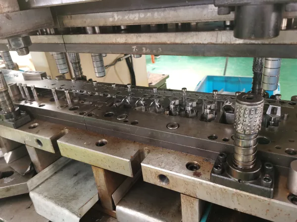
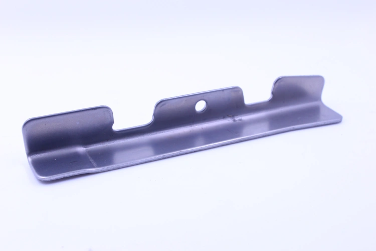
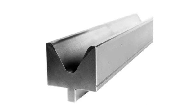
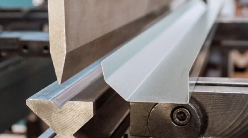

In the field of high-volume hardware manufacturing, a perfect 3D CAD model does not necessarily translate directly into a perfect physical part. To bridge the critical gap between theoretical design intent and the realities of shop-floor manufacturing, strict adherence to Design for Manufacturability (DFM) principles is required. When extending to high-speed progressive die stamping projects, early-stage DFM reviews are by no means mere technical formalities; they are key financial levers for controlling unit costs and maximizing die life.
Engineers often specify micron-level tolerances or extremely sharp internal fillets—parameters that appear perfect on screen but can lead to catastrophic stress concentrations and premature die wear under the immense physical impact of a stamping press. By proactively aligning your design drawings with the metallurgical limitations of progressive die stamping, procurement teams can eliminate supply chain bottlenecks through mathematical calculations before cutting into expensive D2 tool steel.
In this article, we’ll delve into the DFM rules for progressive die metal stamping—from precise punch-to-die clearances to grain orientation—to ensure your next custom progressive die stamping project achieves zero-defect mass production with absolute financial predictability.
Optimizing the Clearance Between the Punch and Die Before Starting Progressive Die Stamping
Optimizing the clearance between the punch and die fundamentally determines the quality of metal trimming and the service life of the die. By engineering the precise shear ratio, the progressive die stamping process can maximize the load-bearing burnish zone, reduce premature fracture, thereby ensuring zero-defect blanks while significantly reducing die maintenance costs.
Calculation of the Ideal Clearance Ratio
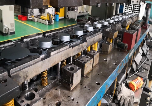
Determining the precise clearance between the punch and the die is a fundamental DFM requirement for any high-volume manufacturing project. As a strict engineering rule, the optimal clearance should be 5% to 10% of the material thickness on one side, with the specific value depending entirely on the metal’s shear strength.
For example, ductile aluminum requires a smaller clearance than high-strength stainless steel. If the clearance is set too wide, the material will be drawn into the die body, causing excessive rollover and resulting in unacceptable burr height. Conversely, a clearance that is too tight will generate severe friction, leading to rapid blunting of the expensive punch.
By calculating the optimal mathematical clearance ratio during the progressive stamping die design phase, Supro MFG ensures clean, load-bearing shear strips. This rigorous approach guarantees that the progressive die stamping process maximizes part quality while avoiding costly die maintenance expenses during production.
Hole Diameter-to-Thickness Ratio (H/T) Constraint
In metalworking, the hole diameter-to-thickness ratio (H/T) is one of the most critical DFM constraints. There is an inviolable rule in mechanical engineering: the diameter of a punch hole must never be less than the thickness of the sheet metal itself. When designers attempt to specify micro-holes that violate this physical constraint, the compressive stress acting on the punch tip will far exceed its buckling strength. In the high-speed environment of progressive die metal stamping, this inevitably leads to catastrophic punch fracture and production line downtime.
If your drawings strictly require a hole diameter smaller than the material thickness, secondary drilling or CNC machining must be performed. By reviewing these critical hole-to-thickness ratios in advance, our progressive die stamping engineers can ensure your drawings are optimized for continuous, zero-defect mass production.
Minimum Bending Radius of Progressive Die Stamping Parts and Material Grain Direction
To master the dynamics of metal bending, tensile stresses must be relieved to prevent the formation of microcracks. By strictly aligning the inner bending radius with the material’s rolled grain direction, progressive die stamping technology can safely form complex geometries without compromising structural integrity or causing fatigue failure.
Determining the Minimum Inner Bending Radius for Progressive Die Stamping Parts
In high-speed progressive die stamping, a key failure point arises when an inner bending radius is specified that exceeds the material’s tensile strength limit. Designing a mathematically acute angle can result in catastrophic stress concentration at the outer bending edge.
A clear DFM rule stipulates that for ductile alloys such as 5052 aluminum alloy, the minimum inner bend radius should be at least 1 material thickness (1T); for high-strength stainless steel, it should be 2T or greater. If the radius is too small, extreme tensile stresses can cause severe microcracks, thereby completely compromising the part’s structural integrity.
By reviewing these radii during the initial CAD review phase, Supro MFG’s die engineers are able to eliminate the risk of punch tip fracture. This proactive DFM optimization ensures that custom progressive die stamping delivers defect-free, fatigue-resistant parts over millions of production cycles.
Understanding Material Grain Orientation
Understanding the anisotropic properties of sheet metal is essential for reliable die design. During the initial rolling process of the raw material, its microstructure develops a distinct grain orientation. A fundamental rule of progressive die metal stamping is that critical bends must be perpendicular to this rolling direction. If the design forces the bending direction to be parallel to the grain orientation, the metal fibers can easily separate, leading to immediate fracture along the bending axis.
When designing strip layouts for high-volume progressive metal stamping, our DFM team precisely calculates the optimal part orientation within the strip. This strategic alignment allows for the seamless absorption of forming stresses, preventing cracks. By adhering to grain mechanics principles, our engineers mathematically ensure that your progressive die stamping part maintains maximum load-bearing strength while avoiding catastrophic production line downtime caused by structural material failure.
Geometric Dimensioning and Tolerancing (GD&T) Strategy for Progressive Die Stamping Parts
The strategic application of GD&T (Geometric Dimensioning and Tolerancing) directly aligns drawing references with the actual mechanical structure of the die, thereby avoiding costly over-engineering. In the progressive die stamping process, striking a balance between strict dimensional control and actual process capability (Cpk) ensures absolute mathematical repeatability while effectively preventing inflated upfront die capital expenditures.
Avoiding Excessive Tolerance Design in the Progressive Die Stamping Process
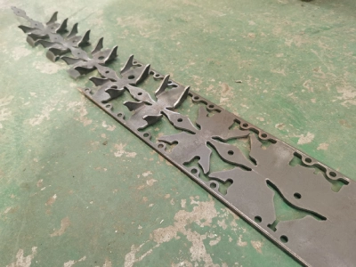
Excessive tolerances are the primary cause of inflated capital expenditures for dies. When engineers indiscriminately apply a tight tolerance of ±0.001 inch to standard server mounting rails or unpaired chassis brackets, they force die manufacturers to use the prohibitively expensive wire-cut EDM process.
For the vast majority of structural hardware, high-precision progressive die metal stamping processes can actually maintain linear tolerances of ±0.005″ while sustaining excellent Cpk stability over millions of stamping cycles. If stricter tolerances are not absolutely necessary for mechanical fit, they are simply a waste of money.
Through rigorous DFM reviews in the early stages, our engineering team systematically relaxes these unnecessary GD&T requirements. This strategic value engineering ensures that your custom progressive die stamping project operates at the highest processing speed, significantly reducing initial die investment and long-term unit costs while ensuring structural integrity.
Selection of Reference Points in Progressive Die Stamping
Establishing appropriate reference points is critical for preventing structural defects during mass production. In the actual manufacturing process, metal strip is fed through the die via precision guide holes. Therefore, to ensure that the theoretical geometric dimensions and tolerances (GD&T) align with actual shop floor conditions, the primary measurement origin (Reference Point A or B) should always be anchored to the positions of these guide holes, rather than to arbitrary shearing edges.
If the blueprint specifies critical hole spacing based on outer boundaries, cumulative tolerance stacking errors will inevitably be introduced. By proactively redefining these reference points during the Design for Manufacturing (DFM) phase, progressive die metal stamping mathematically eliminates unnecessary dimensional offsets. This strict alignment between digital CAD design intent and the physical mechanics of the die enables our quality team to perform First Article Inspection (FAI) with absolute precision, ensuring your progressive die stamping part meets zero-defect compliance standards.
Only 4 steps
online custom metal fabrication parts
Contact our experts team and experience the efficiency and economic benefits of digital metal fabrication services.
Upload Design Files
STL , STEP (.stp), IGES (.igs), (.ZIP), or PDF.
Also be a sample or an idea
Quote & Design Analysis
Instant factory quotes and DfM reports, the most reasonable solution.
Manufacturing Begins
Digital processes can initiate order tasks within 24 hours.
On-Time Delivery
Keeping delivery promises, approved by 3000+ Global Company buyers.
Reinforcing Structural Features of Progressive Die Stamping Parts: Ribs, Flanges, and Extruded Holes
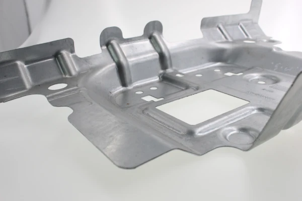
Integrating forming ribs and extrusion flanges directly into the automated progressive die stamping process fundamentally improves part stiffness. This strategic Design for Manufacturability (DFM) technique allows mechanical engineers to specify thinner, more cost-effective sheet metal thicknesses without sacrificing ultimate load-bearing strength or critical threaded engagement performance.
Increasing Stiffness Through Formed Ribs
In the highly competitive industrial enclosure market, reducing material thickness without sacrificing structural integrity represents the ultimate victory in value engineering. By strategically incorporating formed ribs and stiffeners into the design, engineers can significantly improve the bending stiffness of enclosure frames. During the automated forming process, these geometric features are pressed into the metal, thereby altering the cross-sectional moment of inertia to resist severe deflection.
For procurement teams, this means downgrading from thicker-gauge steel to lighter, more cost-effective grades, resulting in immediate and substantial savings on raw materials.
Supro MFG expertly optimizes these rib profiles during the initial DFM review phase, ensuring that your progressive stamping die provides maximum load-bearing stiffness without causing material thinning or severe microcracks at structural vertices.
Design Rules for Extruded Threaded Holes
Securing heavy components to thin sheet metal often leads to stripped threads and severe assembly failures. To address this issue, engineers must replace standard punched holes with extruded flanges. By pressing a specialized punch into the metal, we can stretch the material downward, effectively doubling or tripling the actual depth of the hole walls. This critical extrusion process provides the necessary clearance for subsequent tapping operations, ensuring maximum thread engagement.
However, if the initial pilot hole is sized too small, the metal flange will crack and tear under pressure. When validating high-volume progressive die stamping designs, our tooling engineers rigorously calculate the optimal pre-punch diameter based on the specific yield strength of your material. By optimizing this geometry, Supro MFG ensures the strength of the fastening points while completely eliminating the need for costly welded nuts.
Optimizing Strip Layout in Progressive Die Stamping Production: Maximizing Material Utilization
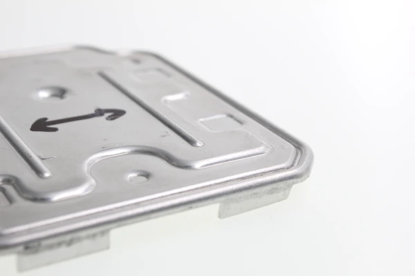
Optimizing strip layout fundamentally determines raw material utilization. Through strategic design of the carrier strip and pitch, progressive die stamping technology can significantly reduce scrap rates, thereby directly translating higher material utilization into substantial cost savings in mass production.
Carrier Strip and Pitch Design in the Progressive Die Stamping Process
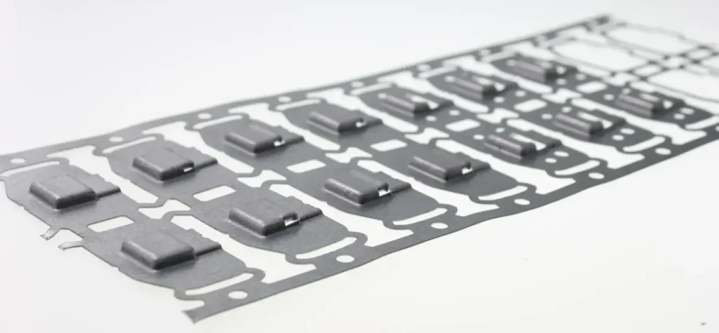
In high-volume metal forming processes, the physical geometry of the parts directly determines the configuration of the scrap skeleton. During the Design for Manufacturing (DFM) phase, engineers must carefully design the carrier ribs and calculate the optimal feed pitch. The carrier ribs must possess sufficient structural strength to prevent buckling under the tension applied by the feeding mechanism, thereby ensuring the smooth transport of the metal strip to each station.
However, if the carrier ribs or pitch dimensions are too large, material waste will increase significantly. By employing advanced nesting techniques, our die experts can optimize the arrangement of parts within the coil width, typically nesting irregularly shaped brackets in an interlocking pattern.
In high-speed progressive die stamping projects, reducing the pitch by just a few millimeters can boost material utilization from 60% to over 85%. For buyers, this strategic progressive die metal stamping layout directly translates into hundreds of thousands of dollars in annual raw material cost savings.
Conclusion: Supro MFG’s DFM Integration and PPAP Compliance
Mastering the manufacturability of progressive die stamping parts is not about limiting engineering creativity, but rather the ultimate strategy for unlocking mass-production efficiency. By proactively integrating our DFM guidelines—optimizing shear clearances, aligning grain orientation, and relaxing non-critical geometric dimensions and tolerances (GD&T)—you can mathematically eliminate premature die wear and catastrophic production line downtime.
At Supro MFG, we seamlessly bridge the critical gap between theoretical CAD models and shop-floor reality. Before launching mass production, our die engineers implement rigorous FMEA risk mitigation measures and adhere to comprehensive PPAP protocols. This stringent automotive-grade validation ensures your custom progressive die stamping projects maintain exceptional Cpk values over millions of stamping cycles, guaranteeing absolute zero-defect compliance.
Don’t let suboptimal design drawings drive up upfront tooling capital expenditures and erode your profit margins any longer. Submit your 3D models to our engineering team today for a comprehensive DFM review, and let our customized progressive die stamping solutions help you maximize your return on investment.