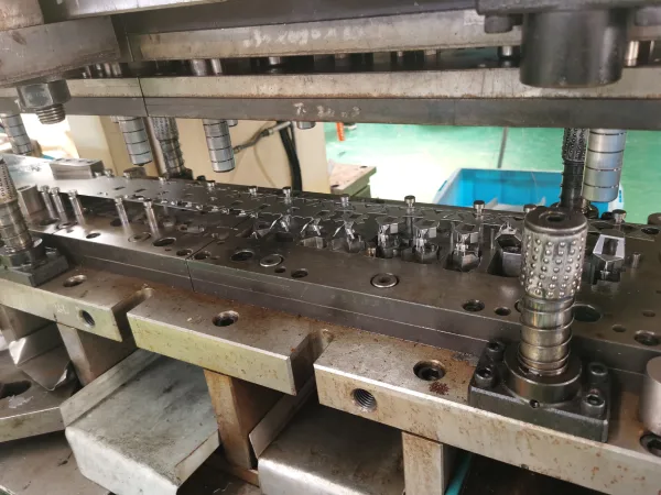

In the field of progressive stamping, zero defects is no longer an ideal goal but a basic requirement. For progressive die stamping manufacturers, the economics of high-speed production further intensify this quality requirement: a single feeding failure or scrap pull-up can destroy a die worth tens of thousands of dollars, cause production to grind to a halt for hours, and compromise the entire production batch.
In-die sensors and protection systems have become critical enabling technologies, making high-speed progressive stamping at over 1,000 strokes per minute economically viable. These systems not only detect problems—they proactively prevent them by stopping the press in time to avoid die collisions, thereby reducing die repair time and significantly improving the yield of perfect parts.
This article will explore the three cornerstone sensor technologies that protect modern progressive die stamping operations: feed error detection probes, scrap (trimmings) lift-off sensors, and bottom dead center (BDC) monitoring systems.
Feed Error Detection: The First Line of Defense in Progressive Stamping
In high-speed progressive stamping, even a feed error of ±0.02 millimeters can cause damage to multiple stamping stations in a single stamping stroke. Industry data shows that feed errors account for 22% of stamping die failures. Traditional sensors operate within the 135–175° range of the press cycle and are unable to stop the slide before it reaches bottom dead center. Therefore, effective detection must identify anomalies within the first 2–5 degrees of the feed cycle—the only time window available to stop the press before the punch engages.
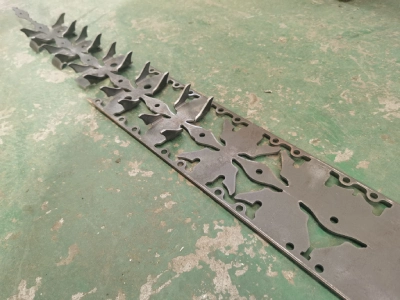
Understanding Feeding Failures in Progressive Stamping
In high-speed progressive die stamping production, feeding failures are one of the leading causes of die damage. Industry data analysis shows that misalignment and feeding failures account for as much as 22% of stamping die failures, resulting in an average of 8 to 14 hours of downtime and repair costs ranging from $1,800 to $5,000. However, the even more sobering reality is that over 90% of unexplained feeding failures in progressive stamping stem from improper calibration of the pilot pin release timing.
The destructive nature of feeding failures lies in their “silent” nature—a lateral feeding error of just 0.05 millimeters is sufficient to simultaneously destroy multiple stations of a progressive die in a single stamping stroke.
In high-speed progressive stamping, the press’s feed cycle is typically fixed at 120 degrees, and failures often occur within the first 2 to 5 degrees of the stamping cycle. This extremely short detection window means that any delay in identification can result in the punch forcing its way down while the material is not properly positioned, causing punch breakage, insert fracture, or even the scrapping of the entire progressive stamping die set.
Therefore, understanding the root causes of feeding failures—including the timing of pilot pin release, feed line height, material sickle bend, and scrap material buoyancy—is the first step in establishing an effective protection system.
Advanced Feeding Anomaly Detection Technology
Traditional whisker wire sensors can only detect whether the strip is touching the probe; their fatal flaw is the inability to distinguish between “normal feeding” and “overfeed.” In the case of overfeed, the tape still contacts the sensor and closes the circuit, sending a false “normal” signal to the press control system, causing the die to continue stamping even when the material is misaligned.
To address this technical bottleneck, a new generation of overfeed/underfeed detection sensors (such as the OKJB series) employs a mechanical verification mechanism: the sensor’s axis must be pushed by the tape into the precise correct position before a “GO” signal is sent to the PLC. This design enables the sensor to independently identify both short feed and long feed anomalies.
In addition, fork-through-beam laser sensors can be used to detect strip buckling and guidance deviations during the feeding process, while high-precision micro-detection systems can measure changes in the clearance between moving die components with an accuracy of 0.00001 inches.
These advanced progressive die stamping sensor technologies, combined with high-speed signal processing capabilities, can identify feeding anomalies and trigger a stop command before the punch contacts the material, thereby fundamentally eliminating accidents involving damage to progressive stamping dies caused by feeding failures.
Best Practices for Progressive Stamping Processes
An effective feed failure detection system for a progressive stamping process involves more than just installing sensors; it requires systematic engineering practices.
First, the sensors must be positioned to detect failures early enough in the stamping cycle—because the press slide has inertia when operating at high speeds, even if a stop signal is received at the 10-degree position, the slide will still reach bottom dead center (BDC) and complete the current stroke. Therefore, sensors must be placed at the station where feeding anomalies first occur—typically in the area before the pilot pin enters the strip.
Second, sensor trigger thresholds must be precisely set: underfeed sensors should trigger only when the feed length is more than 0.012 inches short, while overfeed sensors should trigger when the feed length exceeds the nominal value by 0.012 inches.
Third, sensor selection must take the stamping environment into account—use heavy-duty, oil-resistant cables and install embedded wiring channels within the base of the progressive stamping die to protect the sensor wiring from vibration and stamping lubricants.
Fourth, sensor outputs should be configured as normally closed (“red” sensors) rather than normally open (“yellow” sensors), because a break in a normally closed sensor’s wire is immediately recognized by the control system as a fault and triggers a shutdown, whereas a break in a normally open sensor’s wire may be misinterpreted as “no problem detected.”
Finally, all sensors must undergo bench testing prior to installation to verify their functionality in an actual progressive metal stamping environment.
Scrap (Chips) Pull-Up Detection: Preventing Double-Layer Stamping Accidents in Progressive Stamping
In high-speed progressive stamping, if scrap generated during cutting fails to be properly ejected and remains trapped inside the die (slug pull-up), the next stroke will result in a double-material-thickness condition. Since the detection window spans only a few stamping cycles, any delay in identification means the punch will be forced to stamp through double the material thickness, resulting in punch breakage and die base cracking.
The slug pull-up detection system installs sensors at the stripper plate position to monitor the closing gap in real time and triggers a shutdown before the next stroke in which an anomaly occurs—this serves as the second critical line of defense against catastrophic die damage in the progressive stamping process.
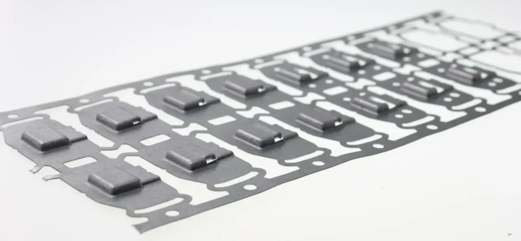
The Hidden Danger of Trapped Slugs
In high-speed progressive metal stamping, if the scrap (slug) generated by the cutting process fails to be ejected properly and remains trapped inside the die, the next stroke will result in a “double-material-thickness” condition, the consequences of which are almost always catastrophic.
This failure mode is insidious because it cannot be detected visually in its early stages—the scrap may adhere to the punch face as it rises, or become lodged inside the die insert without falling out. When the punch forces its way through the double layer of material during the next stroke, punch breakage, die base cracking, and insert shattering are almost inevitable.
What makes this even more challenging is that even if a sensor detects an abnormal rise in scrap, the inertia of the press ram typically makes it impossible to stop the current stroke in time—the detection must trigger a shutdown before the next stroke begins, placing extremely high demands on the response speed of the detection system.
In a progressive stamping process, a single instance of scrap rising is enough to render a die worth tens of thousands of dollars unusable, while also causing hours of downtime losses.
Detection Methods
The core principle of scrap float detection is to monitor the position of the stripper plate during mold closure. The most common method involves installing an eddy-current proximity sensor on the lower die to sample the shortest distance between the stripper plate and the sensor during each stamping cycle. If the stripper plate is lifted by the scrap by even a single material thickness, the sensor immediately detects this height deviation and outputs a stop signal.
High-resolution bottom dead center (BDC) detection systems (such as the PS-464/462 series) can sample the bottom dead center position once per stroke, detecting anomalies such as floating scrap and double-layer stamping with micrometer-level precision.
Micron-level detection systems (micron sensors) go a step further by measuring changes in the gap during die closure—if scrap floats upward and prevents the ejector plate from closing completely, the system immediately identifies the anomaly.
In addition, accelerometers—an emerging detection method—can be mounted on the exterior of the die frame to identify scrap float events by analyzing vibration signals during the progressive die metal stamping process. Some advanced systems can deploy up to four sensors within the die assembly to simultaneously monitor the parallelism and final position of the ejector plate.
Sensor Selection and Installation Considerations for Progressive Stamping Dies
The selection and installation location of scrap lift detection sensors directly determine the effectiveness of the safety system. Sensor placement is a critical decision point: while mounting a sensor behind the upper die stripper plate can detect scrap lift, the sensor itself will be crushed if a foreign object larger than one material thickness enters the die. Therefore, industry best practice is to install inductive proximity sensors on the lower die.
The sensor’s output configuration is equally critical—“normally open” (i.e., “yellow” sensors) indicate “no problem detected” when the wire is broken, preventing the control system from recognizing a fault; whereas “normally closed” (i.e., “red” sensors) are immediately recognized as an abnormal condition and trigger a shutdown when the wire is broken.
In high-speed progressive stamping, the stamping environment is filled with vibration, lubricating oil, and metal debris; sensors must have an appropriate IP rating and use heavy-duty, oil-resistant cables.
The sensor’s trigger threshold must also be precisely set—the gap setting is typically between 0.8 mm and 1.2 mm—as a threshold that is too low will result in frequent false shutdowns, while a threshold that is too high will fail to detect actual scrap rising to the surface. All sensors must undergo bench testing prior to installation to verify their functional parameters.
Only 4 steps
online custom metal fabrication parts
Contact our experts team and experience the efficiency and economic benefits of digital metal fabrication services.
Upload Design Files
STL , STEP (.stp), IGES (.igs), (.ZIP), or PDF.
Also be a sample or an idea
Quote & Design Analysis
Instant factory quotes and DfM reports, the most reasonable solution.
Manufacturing Begins
Digital processes can initiate order tasks within 24 hours.
On-Time Delivery
Keeping delivery promises, approved by 3000+ Global Company buyers.
Bottom Dead Center Monitoring in the Progressive Stamping Process
In high-speed progressive die metal stamping, the immense inertia of the press slide means that even after receiving a stop signal, the current stroke will still reach bottom dead center. The bottom dead center monitoring system samples the die closure position in real time with micrometer-level resolution to detect material thickness anomalies, thermal expansion drift, and die wear, triggering a protective shutdown before the next stroke—this serves as the third critical line of defense for ensuring precision forming.
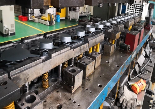
The Critical Importance of Bottom Dead Center (BDC) in High-Speed Progressive Stamping
In high-speed progressive metal stamping, the immense inertia of the press slide makes “stopping before reaching bottom dead center” virtually impossible. Even if the control system issues a stop command at the 10-degree position of the stamping cycle, when the stamping speed reaches 1,000 strokes per minute, the slide will still travel to the 180-degree bottom dead center and complete the current stroke.
This means that the protection strategy for progressive die metal stamping must shift from “preventing the current stroke” to “stopping the machine before damage occurs during the next stroke.”
Compounding the issue, the heat generated by high-speed progressive die stamping continuously alters the bottom dead center (BDC) position—AIDA’s research indicates that thermal expansion during prolonged high-speed stamping causes the BDC position to drift, and only by maintaining BDC accuracy within ±5 micrometers can the forming quality of parts with extremely tight tolerances be guaranteed.
This is where the value of a bottom dead center monitoring system lies: rather than stopping a stroke that has already begun, it captures minute changes in the BDC position during every stroke in real time, triggering protection before problems accumulate into a catastrophe.
BDC Monitoring Technology in Progressive Stamping Processes
Modern BDC monitoring systems use eddy-current proximity sensors mounted on the lower die to sample the shortest distance between the blanking plate and the sensor during each stamping cycle; a microcomputer then calculates the BDC displacement. When the displacement exceeds a preset threshold, the system immediately outputs a stop signal.
The resolution of current mainstream BDC monitoring equipment has reached 0.1 micrometers—for example, the KEYENCE series of sensors achieves a resolution of 0.4 micrometers with a sampling rate of 40,000 times per second, while the SUGIYAMA PS-464/462 series offers selectable resolutions of 1 micrometer or 0.1 micrometer. This level of precision enables BDC monitoring to detect material thickness anomalies, die height drift caused by thermal expansion, and overlapping of stamped parts during high-speed automated progressive metal stamping.
Some advanced systems also support digital filtering and synchronous timing technologies, effectively resisting oil contamination, vibration, and electromagnetic interference, with a false detection rate kept below 0.1%.
Integration with the Press Control System
The effectiveness of a BDC monitoring system depends on its deep integration with the press control system. The monitoring equipment must sample the BDC signal during each stroke and compare the displacement in real time; as soon as an anomaly is detected, it sends a stop command to the press PLC via a relay output.
Modern progressive stamping protection systems support simultaneous connection of up to 32 digital inputs and multiple analog sensors, integrating BDC data with other sensor inputs—such as feed detection and scrap float detection—into a unified protection logic. Ethernet connectivity allows BDC monitoring data to be uploaded to PCs and PLCs, enabling remote monitoring and data analysis.
This integrated architecture enables progressive die stamping facilities to establish a comprehensive stamping process database, which is used not only for real-time protection but also for predictive maintenance and optimization of the progressive stamping process.
Some servo presses go a step further by implementing automatic BDC position compensation—using dedicated sensors to measure changes in BDC position over time and automatically adjusting the position every 100 strokes, with a compensation range of approximately 75 micrometers—thereby maintaining BDC accuracy within ±5 micrometers.
Implement a Comprehensive Progressive Stamping Die Protection Solution
In progressive stamping production, simply installing individual sensors does not constitute protection—truly effective protection depends on systematic procedures. Industry research shows that over 90% of die damage stems from operators bypassing or misconfiguring protection systems, rather than sensor failure itself.
A comprehensive progressive stamping die protection program must integrate sensor selection, threshold settings, installation verification, operator training, and continuous monitoring, upgrading protection from “passive response” to “active prevention”—this is the systematic framework for ensuring zero-defect production in custom progressive die stamping.
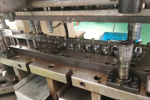
Developing a Progressive Stamping Die Protection Plan
Progressive metal stamping facilities should designate a dedicated die protection technician responsible for system setup, calibration, and maintenance. This individual must receive formal training to systematically learn the components of protection systems and the appropriate applications of different technical solutions. At the same time, operator training must not be overlooked.
When sensors frequently generate false alarms due to improper settings, operators often bypass the protection by repeatedly resetting the system. An effective protection plan must receive clear procedural support from management and establish standardized sensor activation modes and automatic enable counter settings. A well-trained team and comprehensive operating procedures are the institutional safeguards that ensure the protection system functions effectively.
Sensor Selection and Placement
Sensor selection depends on factors such as the type of tooling (box-type ejector plate or spring-type ejector plate), the type of progressive stamping press, speed and stroke, as well as in-die secondary operations (such as riveting or tapping). Sensors are typically positioned at multiple critical locations within the progressive stamping die to detect conditions such as bending, short feed, long feed, scrap float-up, and missed punches.
However, it is important to note that more sensors are not necessarily better—an excessive number of sensors can lead to a disproportionate number of false alarms and production interruptions.
Creative use of sensors allows a single sensor to detect multiple failure modes simultaneously. Installation locations must be determined based on a systematic analysis of potential failure points in the die. Inductive proximity sensors are the most common non-contact detection solution in high-speed progressive stamping. Their solid-state construction has no moving parts and offers inherent resistance to liquids found in stamping environments, such as oil and coolant.
The Role of Bench Testing and Environmental Protection
All sensors must undergo bench testing before being installed in a progressive stamping die. Successful sensor implementation projects all share one key step in common: bench testing.
Environmental factors also determine the service life and reliability of sensors: oils in progressive metal stamping environments often contain microscopic or even macroscopic metal particles, and prolonged exposure can accelerate sensor degradation.
Using heavy-duty, oil-resistant cables and installing embedded wiring channels within the stamping die base ensures effective protection of the sensor wiring. Housing materials and protection ratings must be selected based on the specific environmental conditions of the progressive stamping process.
Conclusion
For modern progressive stamping operations, in-die sensors and protection systems are not optional extras—they are essential infrastructure. Feed anomaly detection probes prevent 95% of die damage caused by feeding irregularities. Scrap float sensors detect this potential threat in time to prevent catastrophic double-stamping accidents caused by pulled-out blanks. Bottom Dead Center (BDC) monitoring provides the precise protection necessary for high-speed progressive stamping.
A comprehensive in-die sensing system reduces progressive stamping die maintenance time, prevents die collisions, minimizes press downtime, and ultimately delivers the flawless parts customers demand. As progressive stamping speeds continue to increase and quality requirements become increasingly stringent, the role of in-die sensors will become even more critical.