
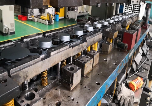
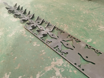
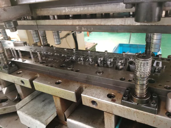

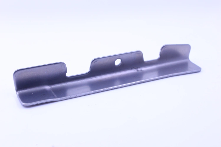
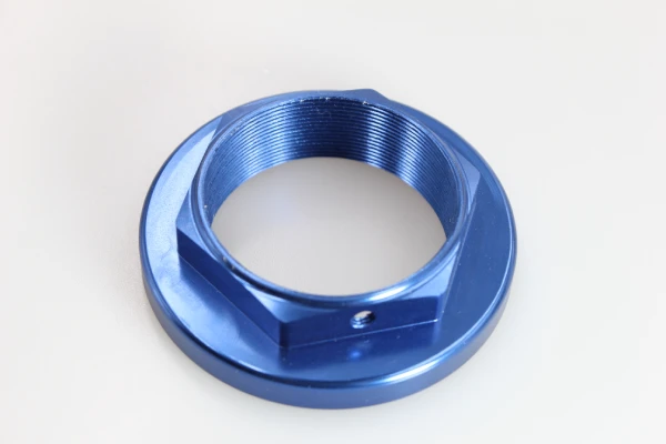
In high-volume sheet metal manufacturing, raw material costs typically account for 60% to 70% of a part’s total cost. When executing high-speed progressive stamping projects, optimizing strip layout is far more than a simple geometric drafting exercise—it is your most critical financial lever.
By strategically calculating the optimal feed pitch and employing advanced interlocking nesting techniques, die experts can significantly reduce residual scrap. Increasing material utilization from the standard 60% to an optimized 85% directly translates wasted coil material into tangible cost savings.
In this comprehensive guide, we’ll delve into the physical principles behind carrier grid design, metal grain orientation, and precision referencing. Learn how our pre-production DFM reviews for the progressive metal stamping process use mathematical methods to ensure the highest material utilization, ultimately achieving the lowest possible unit cost for your custom progressive die stamping projects.
Core Principles of Carrier Strip and Pitch Design in the Progressive Stamping Process
Optimizing the carrier strip and feed pitch fundamentally determines the dynamic behavior of the strip. In high-speed progressive stamping, striking a balance between tensile stability and minimal scrap geometry ensures defect-free coil feeding, prevents catastrophic buckling, and mathematically maximizes material utilization, thereby achieving exceptional cost-effectiveness.
Calculating the Optimal Feed Pitch in the Progressive Stamping Process
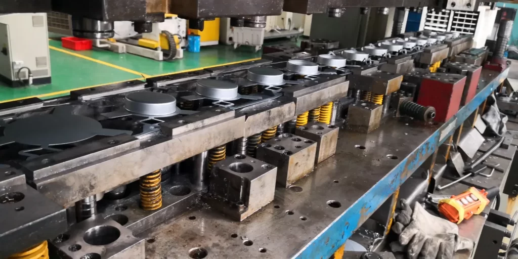
Determining the optimal feed pitch is a fundamental step in reducing the total cost of ownership for parts. The feed pitch determines the exact physical distance the metal coil advances between two stamping strokes. If this parameter is set too large, you are effectively paying for a significant amount of discarded metal web, which severely reduces material utilization. Conversely, if the pitch is calculated to be too tight, there is a serious risk of punch interference and catastrophic web breakage during high-speed progressive metal stamping operations.
To strike the perfect mathematical balance, our die engineers calculate the absolute minimum strip width capable of withstanding internal shear forces. Reducing the pitch by just a few millimeters during the initial Design for Manufacturing (DFM) phase can immediately save thousands of dollars in raw material costs for large-scale custom progressive die stamping projects, without compromising die integrity.
Designing Carrier Strips to Ensure Strip Stability
The carrier strip is the structural lifeline of the material, responsible for seamlessly transporting parts to each precision stamping station. In demanding progressive die metal stamping applications, this continuous carrier strip must possess sufficient tensile yield strength to withstand the immense tensile forces generated by automated servo feeders. If the carrier strip is designed too thin, the coil material will inevitably stretch or warp under tension, leading to catastrophic feeding failures and severe die collisions.
Depending on the specific geometry of the workpiece, die engineers must strategically choose between single-sided, double-sided, or center-supported carrier strip layouts. By precisely analyzing these tensile loads in advance, our progressive die stamping experts design robust carrier strips that ensure absolute stability of the strip, maximizing the continuous runtime of the stamping press while protecting your progressive stamping die from unnecessary impact damage.
Advanced Nesting Strategies to Improve Material Utilization in Progressive Stamping
By adopting advanced nesting configurations, unavoidable scrap can be transformed into tangible profits. Through the strategic interleaving of complex geometries within the coil, progressive stamping technology significantly improves raw material utilization, enabling procurement teams to leverage price advantages in bulk purchases through mathematical calculations without compromising structural integrity.
Material utilization is not a matter of guesswork, but rather a result of rigorous mathematical calculations. During the Design for Manufacturing (DFM) layout phase, die engineers use industry-standard formulas to determine the exact efficiency of the strip layout:
Material Utilization(%)=(Component Area×Number of Cavities)÷(Progression Pitch×Strip Width)×100
By applying advanced layout strategies to directly adjust the denominator (pitch and strip width) or maximize the numerator (cavities), theoretical designs can be translated into quantifiable economic benefits.
Layout Strategy | Typical Material Yield (%) | Scrap Reduction Impact | Tooling CapEx | Ideal Component Geometry |
Standard Single-Row (Linear) | 50% – 65% | Baseline (High Scrap) | Lowest | Simple, rectangular profiles |
Interlocking / Rotational Nesting | 75% – 85% | 15% – 25% Reduction | Moderate | L-shaped, U-shaped, and irregular brackets |
Multi-Row / Staggered (2-out / 4-out) | 80% – 90%+ | Maximum Material Efficiency | Highest (Wider die footprint) | High-volume, symmetrical, or small-footprint parts |
Interlocking and Rotational Part Nesting
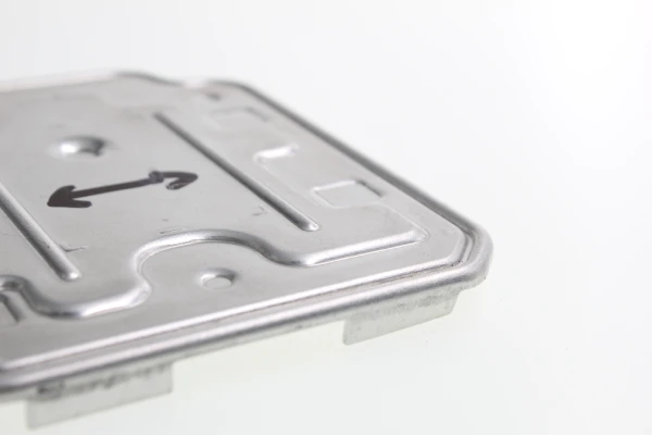
When parts with irregular geometries (such as L-shaped brackets or U-shaped channel sections) are arranged linearly along the coil, they often generate excessive scrap. To effectively minimize this material waste, our die experts employ advanced interlocking and rotational nesting strategies. By strategically rotating these complex parts 90 or 180 degrees within the die, we can make their negative spaces interlock seamlessly.
This precision DFM technique virtually eliminates the dead zones typically left on scrap frames. In high-volume progressive stamping environments, this precise geometric nesting scheme significantly reduces the required strip width. For procurement teams, avoiding these inefficient linear layouts means you no longer have to pay for unused steel. By refining this interlocking structure, our custom progressive die stamping solutions maximize material utilization, directly converting unavoidable scrap into substantial cost savings in your annual production budget.
Multi-Row Layouts vs. Single-Row Layouts
When annual production reaches millions of parts, transitioning from traditional single-row layouts to multi-row configurations becomes a critical financial strategy. Although multi-row dies require higher initial capital expenditures due to their larger coil footprint and more complex die structure, their long-term return on investment is undoubtedly superior. By arranging parts in staggered, double-row, or quadruple-row layouts, engineers can optimize strip edge allowances and significantly improve overall material utilization.
Furthermore, this multi-row architecture can effectively double or quadruple the strokes per minute (SPM) without increasing the actual progressive metal stamping speed. When designing these heavy-duty progressive stamping dies, Supro MFG rigorously evaluates your projected lifetime production volume to determine the precise break-even point. This data-driven approach ensures that your custom progressive die stamping project achieves the absolute lowest cost per unit.
Metallurgical Limitations in the Progressive Stamping Process: Alignment with Grain Direction
When optimizing material utilization, metallurgical integrity must never be compromised. By strategically aligning critical bending areas perpendicular to the rolled grain direction, the progressive stamping process eliminates the risk of microcracks, safely maximizing the utilization of raw material coils while ensuring absolute structural reliability.
Preventing Microcracks Along the Bending Axis
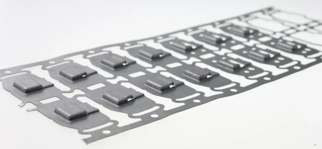
In high-volume metal forming processes, ignoring the material’s rolled grain orientation is a catastrophic engineering flaw. Metal sheets possess inherent anisotropic properties; their fibrous metal structure extends parallel to the initial rolling direction of the rolling mill.
In progressive stamping layout design, there is one non-negotiable rule: the critical bending axis must be strictly perpendicular to this grain direction. If engineers force bending along these grain directions merely to save strip width, the extreme tensile stresses generated at the outer radius will immediately trigger severe microcracks.
This compromised geometry will inevitably lead to in-service failure in heavy-duty structural applications. During the Design for Manufacturing (DFM) phase, our die experts meticulously analyze these metallurgical constraints based on your CAD models. By prioritizing correct grain orientation in progressive stamping dies, Supro MFG completely eliminates the risk of fracture, ensuring that every part can withstand millions of consecutive operating cycles.
Balancing Yield Strength and Structural Integrity in Progressive Stamping Materials
Optimizing material utilization always presents an engineering trade-off: minimizing scrap while maintaining maximum mechanical strength. In complex progressive die metal stamping layouts, arranging parts too tightly to improve material utilization can result in an undesirable parallel alignment of grain orientations. However, sacrificing structural integrity to save a negligible amount of raw material is by no means a viable value engineering strategy.
If a bracket is subjected to dynamic cyclic loads, improper grain orientation can significantly reduce its fatigue resistance, leading to premature structural failure. Our engineering guidelines stipulate that strict metallurgical constraints always take precedence over theoretical scrap savings.
When designing custom progressive die stamping solutions, Supro MFG utilizes advanced simulation technology to identify the optimal layout angles, maximizing coil utilization without ever compromising the metal’s inherent yield strength, thereby ensuring absolute mechanical reliability and long-term cost predictability.
Only 4 steps
online custom metal fabrication parts
Contact our experts team and experience the efficiency and economic benefits of digital metal fabrication services.
Upload Design Files
STL , STEP (.stp), IGES (.igs), (.ZIP), or PDF.
Also be a sample or an idea
Quote & Design Analysis
Instant factory quotes and DfM reports, the most reasonable solution.
Manufacturing Begins
Digital processes can initiate order tasks within 24 hours.
On-Time Delivery
Keeping delivery promises, approved by 3000+ Global Company buyers.
The Role of Precision Guide Holes in Progressive Stamping
In any optimized strip layout, precision guide holes serve as absolute mechanical references. By strictly fixing the internal geometry, the progressive stamping process mathematically eliminates cumulative tolerance stacking, ensuring both high-speed, trouble-free strip feeding and protecting expensive dies from catastrophic collisions caused by feeding failures.
Reference Anchoring to Meet GD&T Requirements
In high-volume production, strict adherence to Geometric Dimensioning and Tolerancing (GD&T) is critical to the success of final assembly. In a highly optimized progressive die metal stamping layout, precision guide holes serve as the absolute physical reference for the advancing coil.
Our die engineers no longer measure actual positions relative to fluctuating sheared edges; instead, they anchor all critical dimensions directly to the positions of these guide holes. This strategic alignment ensures that the reference zero remains mathematically constant as the strip passes through multiple punching and forming stations.
Consequently, this method completely eliminates the risk of cumulative tolerance superposition. By integrating these immutable reference points into the initial strip configuration, our progressive stamping experts ensure that every extrusion flange and punch maintains extremely high Cpk stability, thereby seamlessly passing rigorous First Article Inspection (FAI).
Mitigating Feed Failures and Progressive Stamping Die Damage
In addition to dimensional accuracy, guide holes serve as the ultimate mechanical safety safeguard against catastrophic die damage. Even the most advanced servo feeders are prone to minor deviations during high-speed coil feeding. In a heavy-duty progressive die stamping environment operating at hundreds of strokes per minute, even a 0.002-inch misalignment in material positioning can cause severe punch deflection or result in catastrophic die collisions.
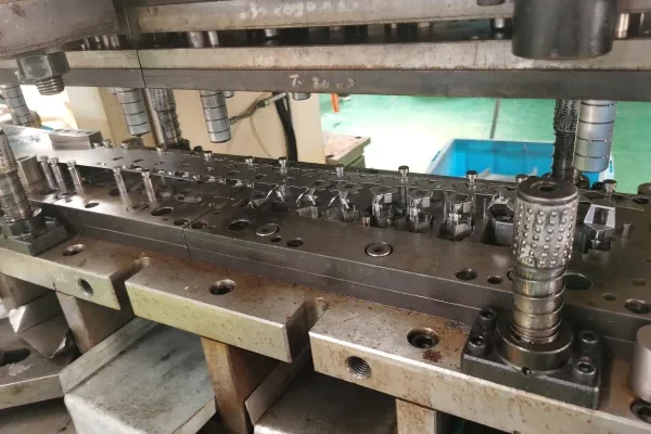
To address this issue, a bullet-head guide pin engages with the strip’s guide hole milliseconds before the main cutting punch strikes, forcibly realigning the material to its precise dead-center position. If engineers fail to allow sufficient strip width for a robust guide station, the entire layout will be compromised. By prioritizing the foolproof engagement of the guide pins, our custom progressive stamping dies seamlessly absorb operational deviations.
This proactive risk mitigation maximizes press uptime and robustly protects your die investment from mechanical failures.
Economic Impact of Progressive Stamping: Scrap Amortization and Return on Investment
By monetizing residual blanks, the progressive stamping process translates optimized material utilization into significant reductions in unit cost, enabling procurement managers to verify long-term profitability across large-scale global production cycles through mathematical calculations.
Monetizing Scrap Skeletons
Even with the most aggressive nesting strategies, physical scrap skeletons remain an unavoidable byproduct of high-volume production. However, this residual metal is not an outright financial loss; rather, it holds significant recycling value. In highly optimized custom progressive die stamping projects, the key to financial accounting lies in accurately calculating the ratio of net part weight to total material consumption.
At Supro MFG, our cost estimators incorporate current scrap metal prices from the commodities market directly into your initial quote. By strategically amortizing the value of recovered scrap against the initial material capital expenditure, we can significantly reduce your final unit part cost. This transparent financial modeling ensures that your investment in precision progressive stamping dies quickly reaches the break-even point, thereby guaranteeing you the absolute lowest total cost of ownership.
Conclusion
Mastering strip layout engineering is the ultimate strategy for transforming theoretical CAD geometries into high profit margins. At Supro MFG, our DFM experts never allow unoptimized blueprints to erode your profit margins. By rigorously integrating advanced interlocking layout architectures, precise metal grain alignment, and foolproof reference points, we mathematically guarantee the highest progressive stamping material utilization.
Before cutting the steel for your progressive stamping dies, our die engineers execute comprehensive PPAP and FMEA protocols. This proactive risk management ensures your dies maintain exceptional Cpk stability, completely eliminating catastrophic feed failures and costly microcracks during millions of high-speed production cycles.
For technical specifications, customized project solutions, or OEM partnership inquiries, please contact Supro immediately. Our professional engineering team is always ready to provide you with tailored application solutions.