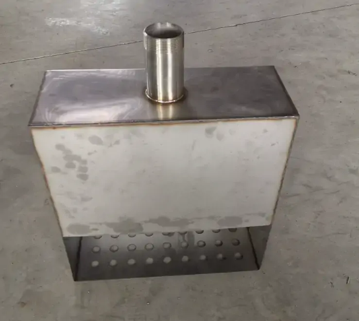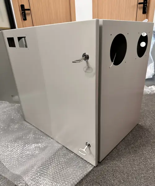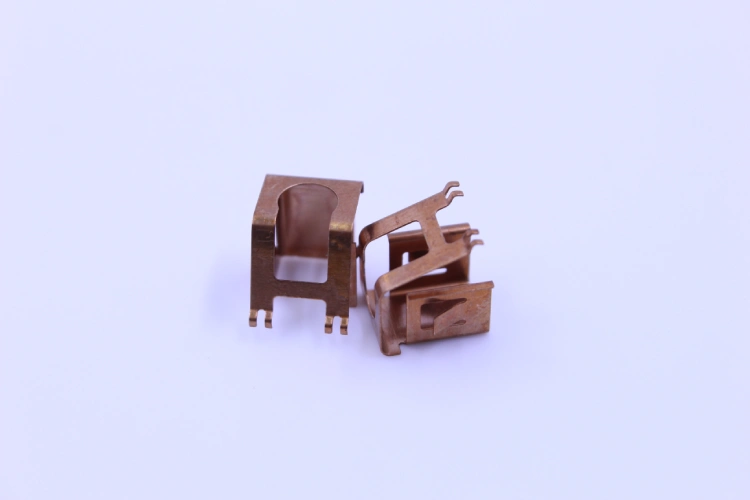
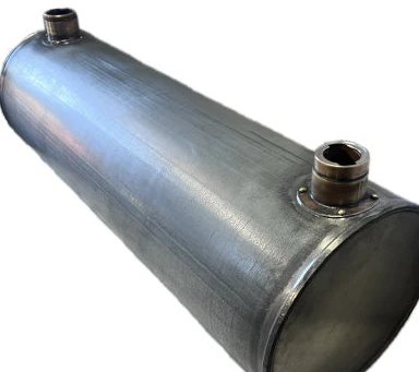

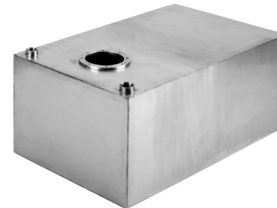
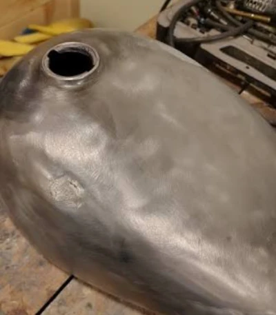

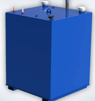

For off-road motorcycles and all-terrain vehicles (ATVs), the mounting ears of metal gas tanks are one of the most frequently overlooked structural weak points in the entire fuel system assembly.
Under the continuous effects of high-frequency vibrations generated by the engine and torsional loads transmitted through rigid connection points, the root of the weld at the junction between the mounting lugs and the metal gas tank experiences cyclic stress amplitudes, which gradually lead to microstructural degradation of the material. Fatigue cracks typically originate at the weld root—where the stress concentration factor is highest—and propagate into the base metal along the path of maximum principal stress.
In one documented case, a 3-millimeter mounting lug welded directly to the wall of a 1-millimeter-thick custom metal gas tank failed multiple times under normal operating conditions, highlighting the importance of thickness matching and load path design. The consequences are not limited to mechanical failure: a cracked mounting lug compromises the integrity of the metal gas tank, leading to fuel leaks and posing a fire hazard in the presence of an ignition source.
Furthermore, repeated repair welding of cracked mounting lugs introduces additional thermal stresses and microstructural degradation, often rendering subsequent repair measures ineffective.
This paper examines the root causes of fatigue fracture in the mounting lugs of custom metal gas tanks from a manufacturing engineering perspective and proposes design strategies—including the use of gussets to alleviate geometric stresses and the adoption of rubber isolators—to transition from a rigid mounting structure to a flexible one, thereby eliminating the transfer of destructive vibration energy to the weld zone.
Understanding the Failure Mechanism of Fracture in Metal Gas Tank Mounting Ears
Fatigue fracture of metal gas tank mounting ears is essentially a phenomenon driven by stress concentration. Cracks originate at the root of the weld, where geometric discontinuities cause local stresses to rise above the material’s strength limit. Under continuous cyclic loads generated by engine harmonics and chassis torsion, microcracks merge and propagate. The following subsections will explore in detail the initiation locations of these cracks and the nature of the cyclic loads.
Fatigue Crack Initiation Locations
In the mounting lugs of metal gas tanks, fatigue cracks originate at the weld root—that is, the transition zone where the weld meets the base metal surface. This location has the highest stress concentration factor (SCF) within the entire joint geometry.
The weld root acts as a geometric notch: the sudden change in cross-sectional shape, combined with microscopic weld discontinuities and the strengthening effect of the weld itself, collectively creates a localized stress field that can reach three times the rated stress or even higher.
Under cyclic loading, this elevated stress leads to the accumulation of dislocations at the microstructural level, eventually forming persistent slip bands that coalesce into microcracks. Subsequently, the cracks propagate into the base metal along the path of maximum principal stress (perpendicular to the load direction).
The weld contains small inherent defects generated by the welding process itself; therefore, the majority of the fatigue life is consumed in the process of propagating these microcracks to critical sizes. This highlights why the geometry of the weld root—including the root radius and groove angle—is the primary determinant of the fatigue performance of metal gas tank mounting structures.
Sources of Cyclic Loads in Off-Road Applications
In off-road applications, the cyclic loads that lead to fatigue failure of metal gas tank mounting lugs primarily originate from two sources: high-frequency vibrations caused by the engine and torsional deflection of the frame.
Engine harmonic vibrations—particularly in single-cylinder and V-twin configurations common in motorcycles and all-terrain vehicles (ATVs)—generate continuous vibrational forces that are transmitted directly through rigid mounting connections. When a metal gas tank is bolted directly and securely to the frame without vibration isolation, these vibrations impose alternating stresses on the weld root at frequencies matching the engine’s rotational speed (RPM)—typically reaching hundreds of cycles per minute during operation.
At the same time, when the vehicle travels over rough terrain, the frame undergoes torsional deformation; this cyclic torsion is converted into out-of-plane bending moments at the mounting lug interfaces of the metal gas tank.
The combined effect of these loads creates a complex multi-axial stress state at the weld root, where both the stress amplitude and the average stress jointly determine the rate of fatigue damage accumulation.
Unlike steady-state driving on highways, off-road conditions subject the mounting structure to loads of varying magnitudes and frequent overload events—such as striking rocks, getting stuck in ruts, and landing after jumps—all of which can lead to local yielding and further accelerate crack initiation. This is why a custom metal gas tank designed specifically for on-road use may fail rapidly when applied to off-road conditions without appropriate design modifications to the mounting structure.
Design Principles for Fatigue-Resistant Mounting Ears on Metal Gas Tanks
The key to designing fatigue-resistant mounting ears for custom metal gas tanks lies in two core measures: reducing stress concentration at welds through geometric optimization—by adding gussets and smoothing transitions—and decoupling the metal gas tank from the vehicle frame’s resonance by integrating rubber isolators, thereby eliminating direct vibration transmission.
Optimizing the Geometry of Metal Gas Tank Mounting Ears to Mitigate Stress Concentration
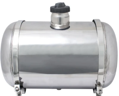
The primary cause of fatigue failure in custom metal gas tank mounting ears is stress concentration at the root of the weld. Due to abrupt changes in cross-sectional geometry, the nominal stress at this location can be amplified threefold or more. The most effective countermeasure is to smooth the load path: adding gusset plates or fillet radii between the mounting lugs and the metal gas tank wall distributes the bending moment over a larger effective area.
Gusset plates—typically triangular or fillet-shaped—reduce the stress concentration factor (SCF) by increasing the stiffness transition length, thereby effectively lowering the peak stress at the weld root.
In the actual manufacturing of metal gas tanks, if space permits, it is recommended to use a fillet radius of at least 6 millimeters at the connection between the mounting lugs and the tank. Additionally, aligning the mounting hole axes parallel to the primary vibration direction can minimize out-of-plane bending.
These geometric modifications result in only a minimal increase in cost during laser cutting and forming processes, yet they significantly extend fatigue life—typically doubling or even tripling the service life of custom metal gas tanks under severe off-road conditions.
Transition from Rigid to Flexible Mounting
Even with perfect geometry, metal gas tanks mounted with rigid bolted connections still pose risks, as the mounting brackets directly transmit engine vibrations and chassis torsional forces. The solution lies in decoupling the metal gas tank from the chassis using elastomeric vibration isolators.
Integrating rubber bushings or vibration isolators at each mounting point, and designing mounting ears with sufficient clearance (typically 2–3 mm of radial clearance) to accommodate the isolators, effectively cuts off the transmission path for high-frequency harmonics.
From the perspective of metal fuel tank manufacturing, this requires pre-stamping a larger mounting hole and may necessitate the addition of a steel sleeve to prevent the rubber bushing from being squeezed out under torque.
Flexible mounting eliminates the cyclic stresses that lead to crack initiation, shifting the failure mode from fatigue to benign wear of the isolators—which are replaceable consumables rather than structural repairs. For any metal gas tank intended for use on unpaved roads, specifying the use of rubber isolators during the design phase is non-negotiable.
Only 4 steps
online custom metal fabrication parts
Contact our experts team and experience the efficiency and economic benefits of digital metal fabrication services.
Upload Design Files
STL , STEP (.stp), IGES (.igs), (.ZIP), or PDF.
Also be a sample or an idea
Quote & Design Analysis
Instant factory quotes and DfM reports, the most reasonable solution.
Manufacturing Begins
Digital processes can initiate order tasks within 24 hours.
On-Time Delivery
Keeping delivery promises, approved by 3000+ Global Company buyers.
Material Selection and Welding Quality Considerations for Mounting Ears on Custom Metal Gas Tanks
For the mounting ears of any metal gas tank, material selection and welding quality are critical factors in determining fatigue life. Mismatched material combinations—such as differences in thermal expansion coefficients or strength—can generate residual stress fields, thereby reducing the fatigue limit. Inappropriate welding parameters can lead to porosity and lack of fusion, both of which can serve as crack initiation points.
Material Compatibility and Formability of Mounting Ears with Metal Gas Tanks
Material compatibility between the mounting lugs and the walls of the custom metal gas tank is a key factor in determining fatigue performance. When a 3-millimeter-thick lug is directly welded to a 1-millimeter-thick tank wall, the significant thickness mismatch causes severe stiffness discontinuity at the joint. The thicker section restricts the natural deformation of the thinner tank wall under load, leading to strain concentration at the root of the weld and significantly reducing fatigue life.
In the mass manufacturing of metal gas tanks, the thickness of the mounting lugs should ideally be within 1 millimeter of the tank wall thickness, or a tapered transition design should be used to ensure a gradual change in stiffness.
Furthermore, the coefficients of thermal expansion of the mounting lugs and the custom metal gas tank material must be highly compatible; welding dissimilar alloys can generate residual stresses during cooling, thereby reducing the joint’s endurance limit.
Aluminum alloys such as 5052 and 5083 are commonly used in metal gas tanks, but their high thermal conductivity and oxide layer characteristics require specialized welding processes. Formability is equally important—the flange material must be able to withstand bending and forming operations without developing microcracks, which could later serve as fatigue initiation points.
Welding Processes and Quality Assurance
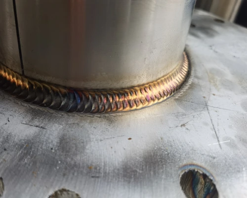
The fatigue strength of welded metal gas tank mounting lugs depends primarily on the weld geometry and process parameters. The transition between the weld and the base metal—particularly the root radius and side angles—directly determines the stress concentration factor at the joint.
Process control during the welding of metal gas tanks must address issues such as incomplete fusion, porosity, and undercut—defects that create sharp notches and thereby accelerate crack initiation.
Welding parameters—including heat input, travel speed, and shielding gas composition—must be optimized for each material combination, as the acceptable parameter ranges vary significantly among different alloys.
For production quality control, visual inspection alone is insufficient; penetrant testing (PT) or magnetic particle testing (MT) should be used to detect discontinuities on the weld root surface.
For any custom metal gas tank intended for severe service conditions, a written welding procedure specification (WPS) accompanied by the corresponding process qualification record (PQR) is an indispensable requirement for ensuring the repeatability of joint quality and the predictability of fatigue life.
Metal Gas Tank Case Study—A Systematic Approach to Failure Prevention
Design principles must be validated through practical application. The following case study documents two instances of failure in the mounting lugs of a metal gas tank during operation. Through a systematic root-cause analysis of the geometry, materials, and joining methods, a targeted redesign was ultimately implemented, resulting in a durable and verifiable solution.
Problem Identification
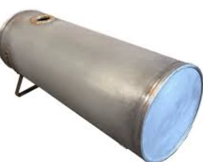
A metal gas tank installed on an off-road all-terrain vehicle (ATV) experienced recurring cracks at the weld toes of its mounting lugs; two previous field repairs both failed within less than 50 operating hours. Inspection revealed that the lugs were made of 3-millimeter-thick low-carbon steel and were directly welded to the 1-millimeter-thick tank wall—this mismatch in thickness caused a significant stiffness transition at the joint.
Finite element analysis confirmed that, under the combined effects of vibration and torsional loads, the stress concentration factor at the weld root exceeded 4.0—far higher than the material’s endurance limit under the observed cyclic spectrum.
Furthermore, the rigid bolted connection directly transmits all engine harmonics to the weld area, and no isolation measures were implemented. A visual inspection revealed that cracks had already formed at the weld root and were propagating along the root toward the thinner base metal.
Therefore, the root cause of this phenomenon in the metal gas tank was determined to be twofold: first, geometric stress concentration caused by the sudden change in thickness; and second, the lack of vibration decoupling measures.
Engineering Solutions
First, a pair of triangular stiffeners was added between the lug and the metal gas tank, increasing the transition radius from essentially zero to a 6-millimeter fillet, thereby reducing peak stress by more than 40%.
Second, the mounting holes were enlarged to 10 millimeters and fitted with rubber bushings (Shore A hardness 60) and steel inner sleeves, transforming the rigid mounting structure into an elastomer-isolated interface, thereby attenuating high-frequency vibrations by approximately 80%.
Third, the welding process for the metal gas tanks was revised: heat input was reduced by 15%, welding travel speed was increased, and the weld beads were ground after welding to form smooth fillets, thereby eliminating sharp notches.
The improved metal gas tank underwent accelerated fatigue testing equivalent to 500 hours of severe off-road conditions; no crack initiation was observed. This case study confirms that, in harsh environments, simultaneously addressing geometric stress concentration and load-transfer structural issues is critical to achieving reliable mounting lug performance.
Quality Assurance and Validation of Metal Gas Tanks
Validating the fatigue resistance of mounting lugs on metal gas tanks requires two complementary approaches: conducting accelerated fatigue tests to confirm their durability under simulated service loads, and implementing production-level quality control to ensure consistency in weld geometry and material compliance.
Fatigue Test Procedure for Metal Gas Tank Mounting Ears
To validate the design of metal gas tank mounting ears, accelerated fatigue testing must replicate the actual service load spectrum—that is, a combination of engine-induced vibration (typically 50–200 Hz) and chassis torsional inputs caused by uneven terrain.
A servo-hydraulic actuator applies sinusoidal or square-wave cyclic loads at the mounting holes, while strain gauges monitor the response at the weld root. The test duration should be set to at least 2×10⁶ cycles without crack initiation, which corresponds to a 2× safety margin for service life. Elevated temperature conditions (e.g., 60°C) may be incorporated to account for thermal degradation in the weld zone.
Production Quality Control for Metal Gas Tanks
During the manufacturing of metal gas tanks, consistency is the foundation of reliability.
The root geometry of each flange weld—fillet weld radius, groove angle, and reinforcement height—must be verified using weld inspection gauges against approved design drawings. At least 10% of the components in each batch should undergo penetrant testing (PT) to detect surface-breaking defects at the weld root.
In addition, dimensional inspections of mounting hole diameters and bushing clearances ensure the correct installation of vibration isolators. Welding parameters for metal gas tanks—current, voltage, and travel speed—are continuously monitored via a data acquisition system; any deviation exceeding ±5% of the approved process parameters triggers an automatic shutdown so that corrective actions can be taken.
As a specialized metal gas tank manufacturer, Supro combines these control measures with traceable material certificates to transform robust designs into consistent, reliable products that consistently meet the demanding requirements of fleet operations.
Looking for a reliable custom sheet metal fabrication companies?
Talk To Supro MFG Expert Team
Contact us for competitive ex-factory prices,
and a full range of technical support services.
Conclusion
Fatigue fracture of mounting lugs on metal gas tanks is not an unpredictable failure mode—it is a design and manufacturing issue with a clear root cause and quantifiable countermeasures.
Stress concentrations can be eliminated by using larger fillet radii and reinforcement plates; rubber isolators can be employed to isolate the gas cylinder from vibrations; material thicknesses can be matched to avoid stiffness mismatches; and weld bead geometry can be controlled through qualified process procedures and post-weld finishing. Both field experience and accelerated testing have confirmed that addressing these factors during the design phase can ensure a predictable and longer service life for the mounting structures of custom metal gas tanks.
Supro is a professional custom metal gas tank manufacturer. With advanced equipment, extensive manufacturing experience, and a professional engineering team, we provide perfect custom metal gas tank solutions to more than 3,000 companies worldwide, along with genuine manufacturer quotes.
If you require technical consultation, system design, or product specifications, please feel free to contact our engineering team at any time.