


Wrinkling is one of the most common forming defects in the deep draw stamping process. This defect manifests as buckling instability in the flange area of the blank when the circumferential compressive stress exerted on the material exceeds its ability to remain stable.
As the punch presses down and pulls the flat blank radially into the deep draw stamping die cavity, the flange material flows inward while undergoing compressive stress perpendicular to the flow direction—when this stress exceeds the material’s buckling resistance, the flange loses stability and undergoes out-of-plane deformation.
From a procurement perspective, wrinkling leads to higher scrap rates, increased costs for subsequent trimming and rework, and extended die trial cycles. To prevent wrinkling, it is necessary to systematically optimize the blank holder force (BHF), die entry radius, lubrication strategy, and material selection. Understanding the mechanical principles of wrinkling and the process parameters that control it is crucial for developing reliable custom deep draw stamping solutions, which ensure consistent part quality throughout the production process.
This article explores the root causes of wrinkling in deep draw stamping, the differences between flange wrinkling and wall wrinkling, and the corrective measures that die designers and process engineers can take.
Mechanism of Wrinkling in Deep Draw Stamping
Wrinkling in deep draw metal stamping is a buckling instability driven by circumferential compressive stress at the flange during radial material flow. If the blank holder force (BHF) is insufficient, it leads to out-of-plane deformation, resulting in wrinkles on the drawn wall surface. The severity of wrinkling increases as the blank diameter increases, the thickness falls below 1.0 millimeters, and the draw ratio approaches the limiting draw ratio.

Compressive Stress and Buckling
Wrinkling in the deep draw stamping process is essentially a compressive instability phenomenon. When the punch presses down and radially pulls the flat blank into the die cavity, the outer edge of the sheet is subjected to tensile stress as well as induced circumferential compressive stress generated along the circumference. When this circumferential compressive stress exceeds the material’s buckling resistance, the outer edge loses stability and undergoes out-of-plane deformation.
As the blank diameter increases, the material thickness decreases below 1.0 mm, and the draw ratio increases, the severity of wrinkling intensifies—all of these factors amplify the magnitude of the circumferential compressive stress. Wrinkling in deep draw stamped parts is caused by excessive compressive stress leading to localized buckling of the sheet metal.
Flange Wrinkling vs. Wall Wrinkling
Flange wrinkling and wall wrinkling are the two primary types of wrinkling encountered in deep draw metal stamping. Both stem from the same fundamental mechanism—hoop compression stress—but differ in their location and susceptibility.
Flange wrinkling occurs in the unsupported region between the blank and the punch face and the blank holder, where the flange material is subjected to the highest hoop compression stress. Both ends of the flange are constrained—one end by the blank holder profile radius and the other by the punch entry point—and out-of-plane buckling occurs when the applied blank holder force (BHF) is insufficient.
In contrast, wall wrinkling occurs in unsupported areas of the drawn wall and is more likely to occur than wrinkling on a flat flange because the wall is relatively unsupported by the die. Controlling wall wrinkling through BHF is more difficult than controlling flange wrinkling because the radial tensile stress component in the wall is harder to regulate.
Studies indicate that approximately 80% of failures in automotive stamped parts can be attributed to wrinkling in the connecting elements (flanges), corner areas, and unsupported drawn wall regions.
Root Causes of Wrinkling in the Deep Draw Stamping Process
The root causes of wrinkling in deep draw stamping lie in imbalances in process parameters and defects in die geometry. Insufficient blank holder force (BHF), excessive die entry radius, oversized blanks with excessively high draw ratios, and inadequate lubrication—each of these factors can, on its own, cause the circumferential compressive stress to exceed the material’s buckling resistance.
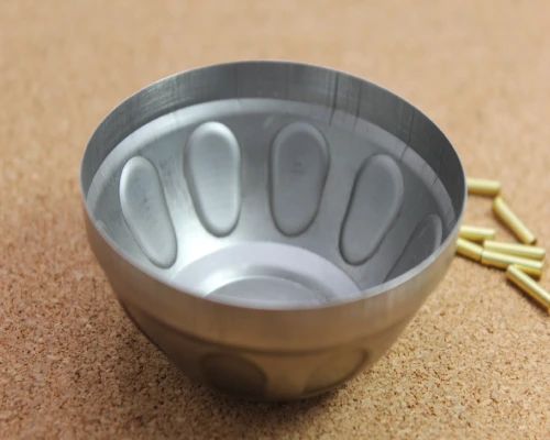
Insufficient Blank Holder Force
Insufficient blank holder force (BHF) is the primary cause of wrinkling defects in custom deep draw stamping. During the stamping process, the blank holder applies constraint around the periphery of the blank to prevent out-of-plane buckling as the material flows radially. When the BHF is too low, the circumferential compressive stress in the flange area exceeds the material’s buckling resistance, causing the flange to buckle due to insufficient restraint.
Studies indicate that buckling occurs when the BHF is less than approximately 1.5% of the material’s yield strength. Insufficient BHF leads to excessive material flow into the die cavity; conversely, excessively high BHF exacerbates thinning and causes tearing. The severity of wrinkling in deep drawn stamping parts increases with larger blank diameters, material thicknesses below 1.0 mm, and higher draw ratios.
Excessively Large Die Entry Radius During deep draw Stamping Production
An excessively large die entry radius significantly increases the risk of wrinkling. When the die entry radius is too large—especially for deep drawn metal stamping of thin-gauge materials—the compressed metal begins to wrinkle before it reaches the vertical walls of the part. This wrinkled metal is then pulled inward as it passes through the die entry radius, increasing flow resistance and potentially even causing the part to crack.
Simulation studies confirm that wrinkling defects appear when the die entry radius increases from 4 mm to 8 mm. The industry-recommended starting value for the die entry radius is 4 to 6 times the material thickness; prioritizing a die entry radius of approximately 6 to 8 times the material thickness during design typically reduces forming difficulty. The die entry must be precisely machined, free of burrs, and polished in the direction of material flow. Additionally, manufacturing the die entry radius from high-wear-resistant tool steel extends the service life of deep draw stamping dies and maintains dimensional accuracy.
Use of Large Blank Diameter and High Draw Ratio in Deep Draw Stamping
The relationship between the blank diameter and the punch diameter—that is, the draw ratio—directly determines the tendency for wrinkling. The limit draw ratio (LDR) is the maximum ratio of blank diameter to punch diameter that can be successfully formed in a single draw operation without wrinkling or tearing; For deep draw grade steel, this value is approximately 2.0.
When the blank is too large relative to the punch, excess material becomes trapped between the die surface and the blank holder, causing a sharp increase in circumferential compressive stress, which in turn triggers flange wrinkling. As the blank diameter increases from 35 mm to 40 mm (raising the draw ratio from 1.75 to 2.0), the tendency for wrinkling increases significantly. deep drawn stamping parts with a draw ratio exceeding 3.0 must employ a multi-stage drawing sequence.
When designing deep drawn parts, the contact points between the forming punch and the metal must be clearly defined, and the distance between the blank edge and the drawing punch must be maintained within the material’s limit draw ratio range. The material’s elongation, n-value, and r-value are critical in the deep draw stamping process.
Insufficient Lubrication in Deep Draw Stamping
Lubrication strategies have a significant impact on wrinkling behavior. In deep draw metal stamping, the die surface and die entry radius must be adequately lubricated to reduce friction and promote material flow. However, the sheet metal on the punch surface should not be lubricated—friction between the punch surface and the workpiece aids the deep drawing process.
When lubricant is applied indiscriminately across the entire blank, the forming behavior may switch between deep drawing and stretching, complicating defect control and leading to inconsistent quality in deep drawn stamped parts.
Insufficient lubrication increases friction at the tool-blank interface, raises the load requirements on the punch, and accelerates thinning in critical strain zones. Lubricants with insufficient viscosity cannot provide adequate restraint in the flange area to suppress buckling caused by circumferential compressive stress. High-viscosity lubricants (100 to 1,000 cSt) effectively prevent surface scratches and reduce punch load. For difficult-to-form materials such as aluminum alloys, lubricants must balance smooth flow with the necessary restraint.
Are you looking for reliable & cost-effective
China metal fabrication manufacturer
More than 150,000 OEM metal fabrication products delivered to 5,000+ global buyers.
And benefit from it!
Detection and Diagnosis of Wrinkling in Deep Draw Stamping
Early detection of wrinkling during the development of the deep draw stamping process can reduce scrap rates and ensure that produced parts meet dimensional requirements. Visual inspection remains the primary diagnostic method for identifying wrinkling in production parts—flange wrinkling typically occurs at the periphery of the part, while wall wrinkling manifests as surface ripples along the drawn side walls.
Wrinkling at or around the punch tip (sometimes referred to as “folds”) indicates insufficient restraint. Finite element (FE) simulation can predict the occurrence of wrinkles in a specific deep draw metal stamping operation before the die steel is cut. Forming Limit Diagrams (FLDs) generated by simulation software identify areas where the material is at risk of wrinkling or tearing—FLDs are graphical representations of sheet metal forming behavior that illustrate the limits of deformation achievable without failure.
In terms of production monitoring, tracking changes in stamping force over time using Statistical Process Control (SPC) can detect process instability before deep drawn stamped parts deviate from specifications, thereby enabling real-time adjustments to the BHF to maintain forming conditions within safe limits.
Prevention and Corrective Measures for Wrinkling in Deep Draw Stamping
To prevent wrinkling in custom deep draw stamping, systematic interventions are required in areas such as BHF, die geometry, and material selection. Each corrective measure is designed to address compression instability—optimizing flow constraints by controlling BHF, adjusting die radii to regulate material draw-in, and selecting materials with higher r-values to resist thinning and buckling.
Optimizing Blank Holder Force in the Deep Draw Stamping Process
Optimizing the blank holder force (BHF) is the most direct and effective measure for preventing wrinkling in deep draw stamped parts. The blank holder regulates the rate at which material flows into the die by applying a predetermined BHF—if the force is too low, the flange lacks sufficient restraint and buckles; if the force is too high, it exacerbates thinning and increases the risk of tearing.
In custom deep draw stamping, the standard practice for correcting wrinkling is to increase the BHF by 10% to 20% and verify the parallelism between the blank holder and the die surface. For circular deep drawn parts made of low-carbon steel, the recommended BHF is approximately 600 pounds per linear inch; for high-strength low-alloy steel and stainless steel, it should be increased to 1,800 pounds. In recent years, variable blank holder force (VBHF) technology has seen increasing application—by applying different force values at different stages of the deep draw stamping stroke, it prevents wrinkling while avoiding excessive thinning.
Segmented blank holders divide the blank holder into multiple independently controlled zones, each applying an optimal force value, which significantly improves the forming quality of irregularly shaped parts.
Setting the spacer height is equally critical—setting it to 105% to 115% of the blank thickness allows room for material compression and thickening; too small a gap restricts material flow, while too large a gap causes wrinkling.
Modifications to Deep Draw Stamping Die Geometry
Adjusting die geometric parameters is the second key measure for suppressing wrinkling in deep draw stamped parts.
The die entry radius directly controls the resistance to material flow into the die—a radius that is too small (less than 4 times the material thickness) restricts material flow, leading to stretching and cracking; a radius that is too large (especially for thin-gauge materials) causes the compressed metal to begin wrinkling before it reaches the vertical wall. The industry-recommended starting value is 4 to 6 times the material thickness; for steel, 6 to 8 times the material thickness typically reduces forming difficulty; Aluminum, due to differences in formability, requires 8 to 10 times the material thickness.
In deep draw stamping dies, draw beads are another key tool for controlling metal flow—they act like “speed bumps,” forcing the material to bend and flatten before entering the die, creating a constraining force that slows and reduces the flow of material. By constraining metal flow, draw beads can reduce the required BHF. The design of the draw bead (height, shape, and dimensions) determines the magnitude of the constraint force. During the debugging phase, metal flow can be adjusted by increasing or decreasing the height of shims to eliminate wrinkling at specific locations.
Material Selection for Deep Draw Stamping
Material selection is the third key factor in preventing wrinkling during the deep draw stamping process. The material’s coefficient of normal anisotropy (r-value) and limit draw ratio (LDR) are critical—materials with higher r-values typically exhibit superior deep drawing performance and higher LDRs. A high r-value indicates that the material is easily deformable in the plane but resists thinning in the thickness direction, thereby reducing the risk of cracking and wrinkling.
For deep draw metal stamping applications, it is recommended to select materials with an r-value greater than 1.5, along with an elongation of at least 40% and an n-value of at least 0.2. In the ASTM A1008 classification system, deep draw grade (DS), deep draw deep draw grade (DDS), and extra-deep draw grade (EDDS) steels offer progressively better formability—EDDS has a carbon content limited to 0.02% or less, providing excellent formability for deep drawn stamped parts with complex geometries.
For stainless steel, 304L (a low-carbon grade) has a yield strength of 35 KSI, making it a superior deep drawing choice compared to standard 304.
Studies have shown that annealed sheets with high n-values, high r-values, and a high tensile strength-to-yield strength ratio exhibit significantly improved resistance to wrinkling. When beginning custom deep draw stamping production, ensure that the material properties match the part geometry and deep drawing depth requirements.
Process Control Strategies for Deep Draw Stamping
To effectively control the custom deep draw stamping process and prevent wrinkling, a systematic approach is required:
First is die trial verification. During die trials, shims are used to adjust the height of the spacers to ensure proper metal flow and eliminate wrinkling at the target locations.
Second is real-time monitoring. Force monitoring is implemented at the punch; when BHF fluctuations exceed ±2.5% of the reference value, the press is triggered to automatically adjust.
Third is lubrication control. Lubricant is applied selectively—to the die surface and the feed radius—while the punch face is kept dry to maintain the deep drawing mode.
Fourth is finite element analysis (FEA) simulation. Before finalizing the die design, the design and process parameters of deep drawn stamped parts are verified through forming simulations. Forming limit diagrams can define a safe forming window for specific material-process combinations.
Fifth is multi-stage planning. Parts with a draw ratio exceeding 3.0 require a multi-stage process sequence. Controlled thinning is performed at each stage, and the optimal BHF value is determined for each drawing step.
Conclusion
In the deep draw stamping process, the key to preventing wrinkling lies in optimizing the blank holder force (BHF) rather than maximizing it, as excessive force eliminates wrinkles at the cost of thinning or even tearing. Metal flow can be further controlled by modifying the deep draw stamping die geometry, including setting the draw flange and reducing the die entry radius. Finite Element Analysis (FEA) simulations enable early detection and process validation prior to production.
Supro MFG applies these engineering principles to every custom deep draw stamping project—from material selection to die trial runs to production monitoring—to deliver wrinkle-free parts that meet dimensional and functional specifications.
For technical specifications or inquiries regarding OEM partnerships, please contact our engineering team.