

For electric vehicle battery packs, the flatness (or coplanarity) of the battery housing’s bottom surface is not merely a dimensional requirement; it is a functional prerequisite that directly affects the thermal management efficiency and structural integrity of the entire energy storage system.
When deviations in the bottom surface of an EV battery housing exceed acceptable tolerance limits, the liquid-cooling plate cannot make tight contact with the bottom surface, creating air gaps that increase thermal resistance and reduce heat dissipation efficiency. At the same time, mounting brackets and cell modules are subject to uneven stress distribution, which accelerates fatigue in welded joints and compromises the long-term reliability of the battery pack.
This article provides an in-depth analysis of the root causes of flatness deviations in battery housing manufacturing and proposes proven countermeasures to ensure consistent compliance with coplanarity requirements.
Definition of Flatness Requirements: What constitutes an acceptable battery housing bottom?
The acceptability of an EV battery housing bottom is defined by coplanarity tolerances, which ensure zero clearance and stress balance with the liquid-cooling plate. The specific standards and their implications are detailed below.
Industry Standards and Typical Tolerance Ranges
Flatness requirements for the bottom of a battery housing vary depending on the application scenario and cooling architecture. Industry practice involves setting tolerances in layers based on functional zones. As the core interface for thermal management, the mounting surface of the liquid-cooling plate typically requires a flatness of ≤0.2 mm; the bottom support plate, which bears the battery modules, typically requires ≤0.5 mm/m²; and the overall flatness error of the welded frame is generally controlled at ≤0.8 mm.
The flatness tolerance range for large battery pack housings typically falls between 0.1 mm and 0.5 mm, with specific values depending on the battery pack capacity, housing material, and structural design.
Sealing surfaces have even stricter requirements, with flatness needing to be controlled within 0.02 mm.
The multi-tiered tolerance system described above reflects the varying flatness requirements across different areas of the battery housing—with the thermal management interface having the strictest requirements, followed by structural support surfaces, and then the overall frame—and manufacturing processes must set control targets for each layer accordingly.
Why Coplanarity Is Critical: Thermal and Structural Impacts
The coplanarity of the battery housing’s bottom surface directly determines the quality of the seal between the liquid-cooling plate and the housing’s bottom surface. When the bottom surface is warped or has localized protrusions, an air gap forms between the liquid-cooling plate and the housing, preventing the thermal pad from making full contact.
The reduced contact area directly lowers heat dissipation efficiency. The resulting increase in thermal resistance forces the thermal management system to operate at higher power, which not only increases energy consumption but may also lead to localized overheating of the battery cells, accelerating aging and even posing a risk of thermal runaway.
Structurally, an uneven bottom surface causes misalignment after the battery module is installed, resulting in uneven stress distribution on the electrical connection terminals. At best, this leads to increased contact resistance and abnormal heat generation; at worst, it can cause terminal loosening or short circuits.
The mounting brackets are subjected to additional bending stress, and the welded joints experience accelerated fatigue under alternating loads. Although deviations in coplanarity may seem microscopic, they are in fact systemic failure factors that affect both thermal management efficiency and structural integrity.

Root Cause Analysis: Why Does the Battery Housing Base Plate Lose Its Flatness?
Loss of flatness in the battery housing base plate is typically caused by stamping springback, welding thermal stress, and insufficient fixture restraint. The combined effect of these three factors can cause flatness to exceed tolerance thresholds; in severe cases, deviations can reach several millimeters. Therefore, systematic intervention is required at the levels of material behavior and process rigidity.
Springback of Battery Housing Material During Stamping and Bending Processes
The battery housing base plate is typically made of high-strength steel or 6xxx-series aluminum alloys to achieve a balance between weight reduction and structural strength. However, the ratio of elastic modulus to yield strength in these materials determines their significant elastic recovery behavior. When the stamping load is removed, the elastic strain energy stored in the material is released, causing the base plate to partially recover its deformation, which manifests as warping or “dish-shaped” indentation of the bottom surface.
For large battery housing trays, the flatness deviation along the entire length of the flange surface can exceed ±1.5 mm due to severe springback. Relying solely on adjustments to process parameters cannot fundamentally eliminate springback; it is essential to incorporate CAE forming simulation (such as AutoForm) during the die design phase to pre-set geometric corrections in the convex die surface—via counter-bow or over-crown—that counteract the direction of springback.
Even after compensation, residual springback may still reach 0.3–0.5 mm, which must be eliminated through precision straightening in subsequent processes.
Heat Deformation Caused by Welding
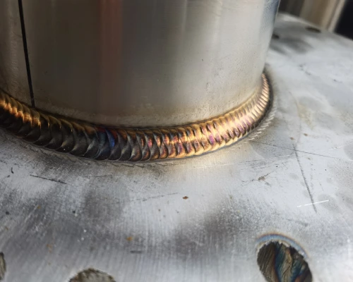
The assembly of the battery housing involves welding processes—including the connections between the base plate and frame, reinforcing ribs, and the top cover and bottom guard plate. During laser or MIG welding, localized heat input causes non-uniform thermal expansion.
Once the transverse residual stresses generated during cooling exceed the critical buckling load of the thin sheet, thermal-induced buckling occurs. The resulting deformation typically manifests as localized warping between weld seams, leading to uneven areas on the bottom surface that cannot be corrected through subsequent assembly steps.
Controlling welding heat input is inherently a thermo-mechanical coupling problem, requiring iterative optimization through a combination of thermo-mechanical finite element simulations and process trials.
Insufficient Fixturing and Process Control in Battery Housing Manufacturing
Deviations in the flatness of the battery housing base plate are often the result of the superposition of residual stresses from the forming and welding processes, and the constraint capability of the fixturing system determines how these stresses are ultimately translated into geometric deformation.
The traditional N-2-1 positioning principle has limitations when constraining thin-gauge, large-sized battery housings.
Furthermore, if the bottom plate already carries residual stresses from stamping before entering the welding station, heat input will further amplify the uneven release of these stresses, leading to unpredictable distortion patterns after welding.
The lack of dedicated flatness correction fixtures and a systematic process validation workflow is the direct cause of many battery housing production lines’ inability to consistently meet flatness tolerances.
Only 4 steps
online custom metal fabrication parts
Contact our experts team and experience the efficiency and economic benefits of digital metal fabrication services.
Upload Design Files
STL , STEP (.stp), IGES (.igs), (.ZIP), or PDF.
Also be a sample or an idea
Quote & Design Analysis
Instant factory quotes and DfM reports, the most reasonable solution.
Manufacturing Begins
Digital processes can initiate order tasks within 24 hours.
On-Time Delivery
Keeping delivery promises, approved by 3000+ Global Company buyers.
Process Strategies: Controlling the Flatness of Battery Housings from Die Design to Final Assembly
Flatness control for battery housings must be integrated throughout the entire manufacturing process—from pre-compensation for springback during the die design phase and process optimization of welding heat input to post-weld hydraulic precision straightening—to form a systematic chain of interventions that ensures consistent achievement of tolerance targets.
Pre-compensation Through Die Design
After the base plate of a custom battery housing is stamped and formed, springback caused by the release of the material’s elastic strain energy is the primary factor leading to deviations of the bottom plane from the design reference. Lightweight materials such as high-strength steel and 6xxx-series aluminum alloys have lower elastic moduli, resulting in more significant springback.
An effective compensation strategy involves incorporating CAE forming simulation (e.g., AutoForm) during the die design phase. By using finite element analysis to predict springback distribution, geometric corrections opposite to the springback direction can be pre-set on the convex die surfaces.
Iterative optimization using stamping simulation can effectively validate the feasibility of springback compensation schemes. After validation through actual trial runs, precision dies can control the flatness deviation of the base plate within an acceptable range. The accuracy of pre-compensation directly determines the input conditions for subsequent welding processes—the smaller the residual springback, the more controllable the final deformation caused by welding heat input.
Optimizing the Welding Process to Minimize Heat Input
Controlling heat input during the welding process directly reduces the magnitude of deformation. The following strategies have proven effective in battery housing manufacturing:
Reduce heat input parameters. Lowering the laser power or adjusting the welding speed can minimize the temperature gradient on the base plate.
Symmetrical welding sequence. Alternating welding positions to balance heat distribution prevents localized deformation in any single area.
Single-side N-2-1 clamping. This clamping principle, specifically designed to constrain thin, easily deformable parts, can significantly reduce transverse residual stresses and buckling deformation during laser welding.
The choice of welding process itself also affects deformation. For example, compared to fusion welding processes, friction stir welding produces lower peak temperatures, thereby reducing thermal deformation in aluminum battery housing components.
Utilizing a Hydraulic Press for Post-Weld Precision Flattening
Even with the strictest controls implemented during the forming and welding stages, large custom battery housing base plates inevitably retain a certain degree of deformation. Post-weld precision flattening—also known as straightening or leveling—serves as the final correction step. It applies controlled localized or global pressure to the base plate via a hydraulic press, inducing slight plastic deformation at high points to correct the overall flatness within tolerance limits.
Compared to mechanical presses, hydraulic systems offer the advantages of stable force output and adjustable pressure control precision, enabling them to maintain a constant load during the pressure-holding phase and thereby prevent overcorrection or stress concentration.
For large battery housing base plates, high-tonnage hydraulic presses equipped with sufficiently large work surfaces can cover the entire bottom surface in a single operation to perform uniform straightening. Post-weld straightening not only corrects geometric deviations but also improves the distribution of residual stresses through localized rolling.
Forming process parameters—pressure values, hold time, and loading sequence—must be specifically set based on the material, thickness, and deformation behavior of the battery housing base plate, and the forming results must be verified through optical scanning.
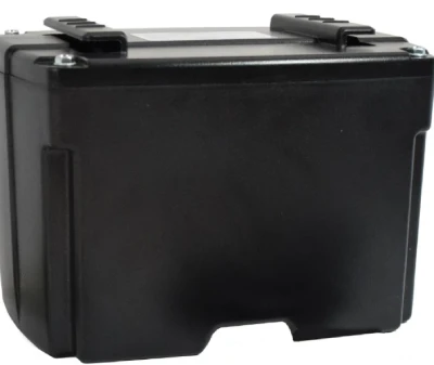
Verification and Quality Assurance: Ensuring the flatness of the battery housing meets requirements
Verification of the flatness of custom battery housings must transition from single-point measurements to full-field characterization—3D laser scanning enables full-surface topography mapping, while granite plates and feeler gauges provide traceable reference standards. Combined with SPC-driven continuous improvement, this forms a closed-loop quality assurance system.
3D Laser Scanning
Traditional contact-based measurement relies on discrete point sampling, making it difficult to fully characterize the topography distribution across the bottom surface of large battery housings. 3D laser scanning uses non-contact optical sensing to capture high-density point cloud data of the entire bottom surface within seconds—scanning time per unit can be reduced to 12 seconds, with a point cloud density exceeding 800 pts/mm².
Compared to traditional CMM spot checks, laser scanning represents a leap from “spot checks” to “100% in-line full inspection.” Measurement data can be directly compared with CAD models, and deviation distributions across the entire surface are visually displayed via color-coded maps to identify local high points, depressions, and distortion patterns.
The GD&T analysis function automatically calculates the flatness and surface profile of sealing surfaces or battery compartment partitions. This solution is particularly suitable for large-sized battery housings, allowing for segmented scanning followed by seamless stitching, with global accuracy controlled at the micrometer level.
This non-contact measurement technology not only enables battery housing manufacturers to identify peak flatness deviations but also to identify the spatial distribution of distortion patterns. The resulting data provides a basis for adjusting battery housing manufacturing processes—for example, if warping consistently occurs between specific weld locations, the welding sequence or fixture strategy can be adjusted accordingly.
Granite Plate and Feelers Gauge Inspection
Despite the growing popularity of optical measurement technologies, the traditional inspection method using a granite plate and feelers gauge remains an irreplaceable benchmark in battery housing shipment inspections due to its traceability and intuitiveness.
The bottom of the custom battery housing is placed face-down on a metrologically calibrated granite platform (the platform’s flatness is typically one accuracy grade better than that of the workpiece being tested). A precision steel straightedge is positioned along the diagonals and in key areas, and a feeler gauge is used to measure the gap between the edge of the straightedge and the surface of the base plate. The maximum thickness of the feeler gauge that can be inserted represents the flatness deviation at that location.
For large battery housings with diagonals exceeding 1,000 mm, inspection must be conducted in sections. Although this method is contact-based and manually operated, its measurement results are directly traceable to international length standards and are not affected by factors such as ambient light or surface reflections.
Statistical Process Control and Continuous Improvement
Compliance with flatness requirements cannot be achieved through inspection alone—it requires continuous process monitoring and adjustment. Laser scan or flatness inspection data for each custom battery housing is entered into a Statistical Process Control (SPC) system to generate X̄-R control charts for flatness metrics or trend charts for capability indices (Cp/Cpk).
When the control chart shows a continuous upward trend or a single data point exceeds the control limits, the system automatically issues an alert, prompting the engineering team to investigate potential causes such as mold wear, laser power drift, or hydraulic press pressure fluctuations.
While flatness deviation is essentially a “pass/fail” count-type metric, the measurement data regarding the magnitude of the deviation also holds value for process diagnostics—a gradual increase in the mean deviation often indicates that the mold is entering the mid-stage of wear, necessitating preventive maintenance. Through SPC’s closed-loop feedback, the flatness pass rate for battery housings has gradually improved from an initial 92% to over 99%, achieving a transition from “inspection-based quality” to “design-based quality.”
Looking for a reliable custom sheet metal fabrication companies?
Talk To Supro MFG Expert Team
Contact us for competitive ex-factory prices,
and a full range of technical support services.
Conclusion: Supro MFG’s Approach to Controlling the Flatness of Battery Housings
At Supro MFG, we view the flatness of custom battery housings as a systemic issue rather than a challenge confined to a single process step. Our approach integrates the following elements:
Die design with springback compensation, utilizing advanced forming simulation technology to predict and correct material behavior before the die steel is cut.
Controlled welding parameters and fixtures that minimize distortion at the source by reducing heat input and utilizing specialized clamping devices.
Post-weld hydraulic straightening, where precision straightening corrects residual deviations without compromising structural integrity.
100% flatness verification, where we use 3D laser scanning or granite plate inspection to ensure every product meets tolerance requirements before shipment.
Supro is a professional battery housing manufacturer. Our quality management system, certified to ISO 9001:2015 and IATF 16949:2016, ensures full traceability throughout the entire process, from material receipt to final inspection.
We deliver a wide range of products efficiently and on time. From product design and rapid sheet metal prototype fabrication to mass production, we provide professional technical support and exceptional quality. We also offer one-stop manufacturing solutions and highly cost-competitive product supply!
For technical specifications or inquiries regarding OEM partnerships, please contact our engineering team.