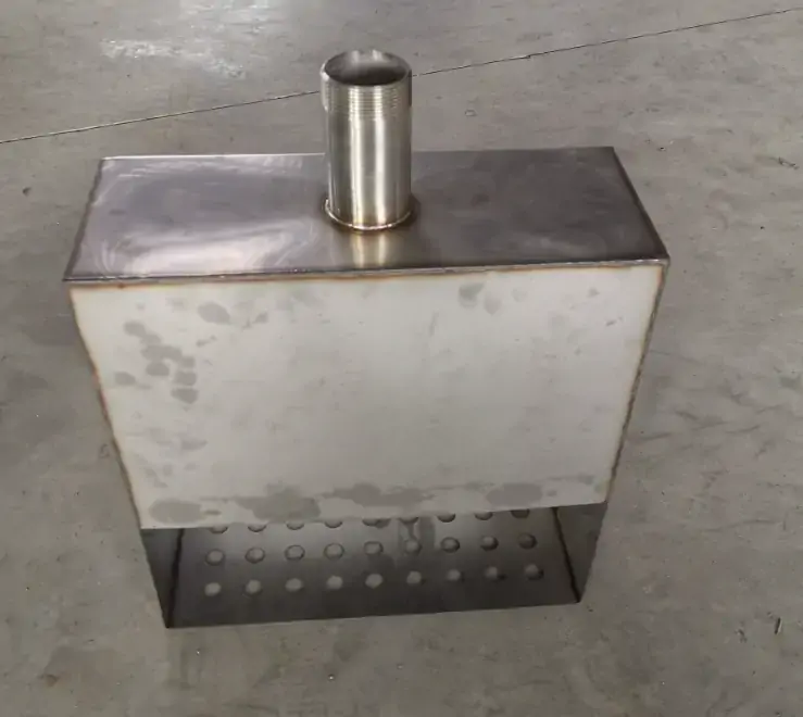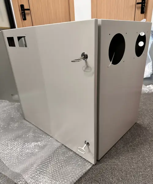

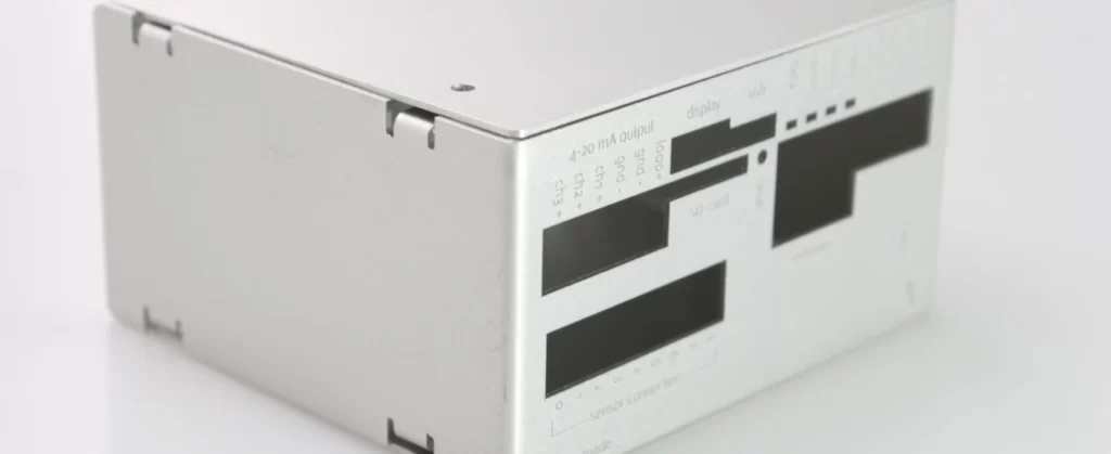

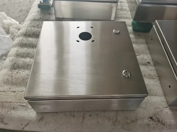
For electrical junction boxes, the quality of the concentric knockout holes directly determines the product’s usability and safety during on-site installation.
An ideal junction box knockout should remain securely attached during transportation while allowing for clean removal with minimal force at the construction site, without the need for additional tools or secondary trimming.
However, in actual production, two conflicting failure modes are frequently encountered: the knockout is too loose and falls out prematurely during transportation; or it is too tight, forcing installers to use hammers and chisels to knock it out, resulting in deformation or even cracking of the box walls. These two defects not only increase on-site rework costs but may also pose electrical safety hazards due to compromised structural integrity of the custom junction box.
To systematically address punching defects in electrical junction boxes, it is essential to address three dimensions simultaneously—die maintenance protocols, optimization of micro-fit parameters, and clearance matching—to establish a process control system covering the entire stamping process.
Identifying Punching Defects in Junction Boxes
To accurately identify punching defects in custom junction boxes, one must begin by examining two types of on-site failure modes: loosening and jamming. The former indicates insufficient holding force in the micro-connector, while the latter reveals die wear or clearance mismatch. Both types of defects point to systemic deviations in the stamping process control, and diagnosis is a prerequisite for subsequent root cause analysis.
Loose Perforated Parts—Premature Detachment During Transportation
Loose perforated parts manifest as premature fracture of micro-joints under transportation vibrations and stacking loads, causing the perforated components to detach from the box. The direct consequence of this defect is that the openings in the box lose their protective sealing, potentially requiring additional protective measures at the construction site due to the intrusion of foreign objects.
The root cause of this phenomenon in electrical junction boxes lies in the shear clearance between the punch and the die exceeding the design tolerance—when the clearance is too large, the remaining material thickness of the micro-joints is insufficient to ensure adequate holding force.
For junction boxes processed using an NCT (CNC turret punch press), the number, width, and distribution of micro-joints are all determined by programming parameters. If the programming has not been optimized for the specific sheet thickness and grade, the holding force of the punched parts may still fall below the threshold required for transportation, even if the die is in good condition.
Stuck Punching Parts—On-Site Rework and Junction Box Deformation
Stuck punching parts manifest as installation personnel having to use a hammer and chisel to forcefully remove them; during this process, the walls of the custom junction box often undergo irreversible plastic deformation. Deformed box walls may prevent conduit connections from fitting tightly or affect the installation clearances and electrical safety distances of internal components.
The root cause of this defect lies in punch wear, which dulls the shearing edge—a worn punch cannot form a clean, consistent shearing profile on the material, resulting in residual joint strength in the micro-joint area that far exceeds the design value. At the same time, if the die clearance is less than the optimal ratio of the sheet thickness (typically 10%–15%), the material undergoes excessive compression during shearing, resulting in work hardening that further increases the fracture resistance of the micro-joints.
For mass-produced electrical junction boxes, punch wear is a gradual and insidious process deviation that often persists for an extended period before batch defects become apparent.
Costs Resulting from Punching Defects in Production and Installation
The costs associated with punching defects encompass both the manufacturing and on-site installation phases. On the manufacturing side, loose components can fall out during transportation, increasing labor costs for sorting and resealing, and may even lead to customer complaints and returns.
During installation, jammed components force electricians to use unconventional methods to remove the punched parts on-site, extending the installation time per junction box; if the box walls are severely deformed, the entire box must be replaced—industry data shows that the labor and material costs for a single on-site rework of an electrical enclosure can reach thousands of dollars.
Furthermore, both types of defects may pose safety hazards due to compromised structural integrity of the electrical junction box; the resulting costs of quality traceability and liability determination often far exceed the direct expenses of rework.
Analysis of the Causes of Punching Defects in Junction Boxes—Die and Programming Factors
The root causes of punching defects in custom junction boxes can be attributed to three interrelated process variables: progressive wear of the punch and die, the accuracy of NCT micro-joint programming parameters, and the match between die clearance and sheet thickness. A deviation in any one of these three factors will alter the shearing profile and residual holding force of the punched part, thereby causing field failures such as loosening or jamming.
Punch and Die Wear in High-Volume Junction Box Production
During continuous punching, punches and dies are subjected to high-frequency impacts and shear stresses, making the blunting of their cutting edges an inevitable, progressive process.
For the concentric punching of custom junction boxes, the radius of the punch cutting edge increases with cumulative punching cycles, and the shearing action gradually degenerates into tearing. A dulled punch cannot form a smooth sheared surface on the sheet metal, causing the residual connection strength in the micro-joint area to rise—even if the original programming parameters remain unchanged, the actual extraction force required may be several times greater than the design value.
Furthermore, microscopic changes in the die clearance caused by prolonged impact further exacerbate inconsistencies in the shearing profile. In batch junction box fabrication, wear is insidious and cumulative, often going unrecognized until batch defects become apparent; therefore, establishing a preventive maintenance system based on punch count—rather than passive, reactive replacement—is a fundamental prerequisite for controlling the consistency of junction box punching.
Programming Errors in Micro-Joints for NCT Turret Punch Presses
The parameters of micro-joints—including the number of joints, geometric width, distribution positions, and residual thickness—are all precisely defined in the NCT programming file.
For perforated components in custom junction boxes, micro-joint design requires striking a precise balance between the holding force during transport and the force required to detach them on-site. Programming errors commonly occur in the following scenarios: failure to adjust the residual thickness ratio for specific material grades; joint distribution that does not account for stress concentration zones in the perforation pattern; or directly applying the same program to sheets of different thicknesses without making appropriate adjustments.
When the total holding force of the micro-joints is too high, excessive external force is required to remove them on-site, causing the electrical junction box to deform; when it is too low, the joints loosen prematurely during transport. Precise micro-joint programming should involve differentiated design based on specific material thickness and mechanical properties, supplemented by process validation tests to confirm that the actual removal force falls within an acceptable process window.
Mismatch Between Die Clearance and Sheet Metal Thickness
Die clearance—that is, the radial difference between the punch’s outer diameter and the die’s inner diameter—is a core parameter determining shear quality. For the sheet metal used in junction boxes, the optimal clearance is typically 10% to 15% of the sheet thickness.
If the clearance is too large, the material undergoes tensile tearing during the shearing process, resulting in uneven residual material thickness in the micro-joint area and increased variability in holding force; if the clearance is too small, the punch and die exert excessive compression on the material, causing secondary shearing and burrs on the shear surface, which significantly increases the actual fracture resistance of the micro-joint and consequently increases the extraction resistance during field installation.
More critically, if the same set of dies is used for junction box sheets of different thicknesses without adjusting the gap, the aforementioned issues will be further exacerbated. Therefore, the die gap must be verified and adjusted for the nominal thickness and tolerance range of each batch of material to ensure that the shearing process remains within the balance between tension and compression.
Only 4 steps
online custom metal fabrication parts
Contact our experts team and experience the efficiency and economic benefits of digital metal fabrication services.
Upload Design Files
STL , STEP (.stp), IGES (.igs), (.ZIP), or PDF.
Also be a sample or an idea
Quote & Design Analysis
Instant factory quotes and DfM reports, the most reasonable solution.
Manufacturing Begins
Digital processes can initiate order tasks within 24 hours.
On-Time Delivery
Keeping delivery promises, approved by 3000+ Global Company buyers.
Solutions for Junction Box Stamping Quality
To systematically address punching defects in custom junction boxes, a three-pronged approach must be implemented simultaneously: die maintenance protocols, calibration of micro-fit parameters, and die clearance matching. Only through the coordinated optimization of these three elements can the stamping process be maintained within a stable process window, ensuring that punched parts offer both transport stability and on-site stampability.
Implementing a Rigorous Die Maintenance Plan During Junction Box Fabrication
For high-volume stamping production of junction boxes, the die maintenance system should shift from a reactive to a proactive approach. Specifically, a service life record should be established for each die based on a stroke counter, including cumulative stroke count, cutting edge measurement data, and replacement history. When the cumulative stroke count of a punch reaches a preset threshold—such as a maintenance cycle determined by material thickness and grade—the cutting edge should be ground or the entire punch replaced, rather than waiting for defects to appear before taking action.
In addition, a die condition verification should be performed before each batch of junction box fabrication, involving test punching with standard test pieces to measure shear surface quality and micro-joint dimensions. For concentric holes with critical dimensions, a projector or profilometer should also be used periodically to monitor trends in punch edge radius changes, ensuring they remain within acceptable tolerances.
Systematic maintenance records not only ensure the consistency of electrical junction box punching but also provide a data foundation for continuous process optimization.
Precision Micro-Joint Design Based on Material Thickness
Micro-joint design parameters are not fixed values but should be set differently based on the thickness and grade of the sheet metal used for the junction box. Key control variables include: the number of micro-joints, the width of each joint, their distribution, and the proportion of residual material thickness.
For thinner sheet metal (e.g., less than 1.0 mm), the number of micro-joints should be moderately reduced, and the residual thickness ratio should be controlled between 20% and 30% to avoid excessive pull-out force that could make on-site punching difficult; for thicker sheet metal (e.g., 2.0 mm or more), the number of joints or the width of each joint should be increased to ensure sufficient holding force during transportation and handling.
Additionally, the placement of micro-joints should avoid stress concentration zones around the cutout contour—such as the four corners of a square cutout—to prevent unexpected fractures caused by stress concentration during transportation. Each set of micro-joint parameters must be verified through actual pull-out force testing before mass production of junction boxes begins, to ensure they fall within the process window jointly confirmed by the manufacturer and the customer.
Optimizing Die Clearance for Specific Sheet Thicknesses
Die clearance optimization should be precisely matched to the nominal thickness of the sheet metal used for the junction box and its actual tolerance range. The general principle is to set the clearance value at 10% to 15% of the sheet thickness; however, for high-strength low-alloy steel or coated sheets, this ratio must be appropriately adjusted to compensate for the material’s work-hardening characteristics.
When multiple sheet thicknesses are involved in the same electrical junction box product, adjustable-gap dies should be used, or a dedicated die set should be configured for each thickness to avoid the practice of “using a single die set for all thicknesses.”
Prior to mass production, the reasonableness of the gap settings should be verified through quality inspections of the sheared surfaces—including the proportion of clean edges, burr height, and cross-sectional skew. Additionally, the actual gap when the die is closed should be measured directly using standard thickness gauges on a regular basis. The measurement results should be compared with the design values and recorded, serving as a key control indicator for the stability of the custom junction box stamping process.
Best Practices for Junction Box Fabrication
Best practices involve systematizing and institutionalizing the aforementioned solutions to establish a closed-loop control system covering the entire stamping process for electrical junction boxes. From process monitoring and tool management to shipment verification, standardized operating procedures at every stage directly impact the consistent quality of punched parts.
Statistical Process Control in the Stamping Process
Statistical Process Control (SPC) is the core tool for shifting junction box punching quality from “post-production inspection” to “in-process prevention.” In practice, control limits—both upper and lower—should be established for the key quality characteristics of concentric punching, including hole diameter, residual thickness at micro-joints, and pull-out force. Samples should be taken at fixed intervals during production for measurement, and the results plotted on control charts.
When measured values exceed control limits or show a continuous trend deviation, this triggers a process investigation and mold condition inspection, allowing for intervention before defects occur.
For high-volume orders of electrical junction boxes, the SPC sampling frequency should be dynamically adjusted based on the process capability index (Cpk)—increasing sampling frequency when process capability is insufficient and moderately relaxing it when capability is sufficient. The long-term accumulation of SPC data can also be used to identify differences in mold wear rates and material batches, providing quantitative evidence for the continuous optimization of process parameters.
Junction Box Mold Selection and Preventive Replacement Procedures
Die selection should be based on a systematic evaluation of the junction box’s product specifications and production batch size. For long-term, high-volume orders, priority should be given to punches and dies made of powdered high-speed steel or cemented carbide, as their wear resistance and service life are significantly superior to those of conventional tool steel.
Upon die acceptance into inventory, the initial cutting edge profile and dimensional parameters of each die set should be recorded, and a unique identification code should be assigned to each, linked to the production logs of the NCT equipment.
The core logic of the preventive replacement procedure is to establish a punch life model based on historical wear data and trigger replacement based on punch count, rather than relying on on-site inspections to detect defects before shutting down production for repairs.
For high-specification custom junction boxes, a “rotating spare die set system” may be adopted—that is, before the currently used die reaches its service life threshold, a pre-ground spare die is already prepared for installation, enabling a zero-downtime switchover.
Quality Verification at the Press—Prior to Shipment
Pre-shipment quality verification serves as the final line of defense for controlling punching defects in junction boxes and should be conducted at the press, either inline or near-line.
Verification includes: using go/no-go gauges to check whether the inner diameter of the cutouts meets specification requirements; using a contour projector or optical measurement system to confirm the geometric dimensions and residual thickness of the micro-connectors; and performing sample extraction force tests, using a push-pull force gauge to measure the peak force required to remove the cutout parts from the box.
As a professional junction box manufacturer, Supro conducts first-piece, in-process, and final inspections for every production batch, and provides a written inspection report with each shipment. For junction boxes exported to the North American market, we also incorporate relevant mechanical performance test items into our verification procedures in accordance with the requirements for opening strength and installation torque specified in UL 514A or ANSI/NEMA standards, ensuring that our products meet the compliance requirements of the target market.
Looking for a reliable custom sheet metal fabrication companies?
Talk To Supro MFG Expert Team
Contact us for competitive ex-factory prices,
and a full range of technical support services.
Conclusion
The stamping quality of concentric holes in junction boxes is essentially the result of the synergistic interaction of three process variables: die condition, micro-joint programming, and clearance matching. Although the two types of on-site failure modes—loosening and jamming—manifest differently, their root cause points to insufficient process control precision in the stamping process. The core of a systematic solution lies in shifting the focus of quality control to the process design stage—moving from passively responding to defects to actively predicting and controlling process deviations.
For junction box manufacturers, establishing a closed-loop control system that covers die maintenance, parameter calibration, and process monitoring is not only a technical safeguard against batch defects but also a necessary prerequisite for meeting market demands for product traceability and compliance in electrical enclosures. Ultimately, reliable punch-formed part quality translates into installation efficiency at construction sites and long-term safety for end users.
Supro MFG is a China-based precision junction box manufacturer certified to ISO 9001:2015 and IATF 16949:2016. With in-house tooling capabilities, CAE simulation expertise, and a commitment to process control with a CPK > 1.33, we provide one-stop custom junction box manufacturing solutions to global customers in the electronics, industrial, and telecommunications sectors, along with genuine manufacturer quotes.
For inquiries regarding technical specifications, customized project solutions, or OEM partnerships, please contact Supro immediately. Our professional engineering team is always ready to provide you with tailored application solutions.