
In the field of custom metal fabrication, precision determines price. Unnecessary geometric precision remains one of the biggest factors driving up Bill of Materials (BOM) costs in CNC machining. When engineering teams automatically apply the strict tolerances listed in the drawing header to every dimension, they inadvertently require low feed rates, secondary finishing, specialized toolpaths, and rigorous Coordinate Measuring Machine (CMM) inspections for non-critical features.
To achieve cost-effective manufacturing, a pragmatic Design for Manufacturability (DFM) approach is required: reserve tight tolerances (±0.0005” / ±0.01 mm) only for critical bearing interfaces, locating pins, or dynamic seal seats, while applying standard commercial tolerances (ISO 2768-m) to open features. By aligning dimensional requirements with actual functional needs rather than theoretical perfection, procurement teams can optimize custom CNC machining cycles, reduce scrap rates, and significantly lower overall production overhead costs without compromising the performance of structural components.
How CNC Machining Tolerances Directly Affect Machine Shop Expenses
Tight tolerances directly drive up the overhead costs of a CNC machining shop, as they require slower cutting parameters, specialized carbide cutting tools, a temperature- and humidity-controlled inspection environment, and higher scrap allowances—thereby transforming minor geometric variations into significant cost multipliers throughout the machining production process.
Equipment Selection and Machine Hourly Rates
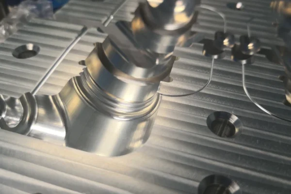
Dimensional tolerances directly determine the level of equipment required for production. Standard machining tolerances (± 0.10 mm) can be reliably achieved using a standard three-axis vertical machining center. However, to meet tight tolerances (± 0.005 mm), shop planners must schedule parts for machining on high-end five-axis machining centers equipped with linear glass scales, thermal compensation algorithms, and high-rigidity spindles. The resulting difference in indirect costs is significant:
Hourly rates at a CNC machining shop jump from $65/hr for standard equipment to over $150/hr for ultra-precision machines. Furthermore, high-precision CNC machining setups require rigid fixtures and dedicated machine calibration cycles to prevent positioning drift. When non-critical features are also subject to tight tolerances, the procurement team is effectively paying high machine tool costs for geometric accuracy that adds no functional value to the final assembly, which significantly drives up the unit cost of both prototype and high-volume metal CNC machining production runs.
Cutting Tool Wear, Deflection, and Feed Rates
Strict CNC machining tolerances force machine operators to adjust cutting parameters, thereby driving up labor and consumable costs. To suppress vibration and minimize tool deflection during machining, programmers must reduce the depth of cut (DOC) and feed rate—sometimes by as much as 60% or more. This significantly extends machining cycle times.
Furthermore, maintaining tolerances of less than one thousandth requires the use of specialized microcrystalline carbide tools and frequent tool changes. Even if the cutting edge wears by only a few micrometers, dimensional deviations accelerate, causing CNC-machined parts to deviate from specifications.
In high-speed CNC machining, maintaining strict tolerances on difficult-to-machine alloys such as 316 stainless steel or Ti-6Al-4V rapidly increases tool wear costs. Machine operators must frequently adjust offsets, add extra pre-cutting passes, and continuously monitor tool wear—this non-value-added downtime is directly passed on to the supplier’s final quote.
Quality Control, Inspection, and Scrap Rates
The economic burden of overly tight CNC machining tolerances is not limited to the cutting area; it also affects quality assurance and shop floor yield. Standard commercial dimensions can be quickly verified right next to the machine tool using handheld calipers or optical comparators. In contrast, strict tolerance requirements necessitate offline inspection using a fully automated coordinate measuring machine (CMM) in a temperature- and humidity-controlled quality laboratory.
CMM programming, probe calibration, and thermal stabilization cycles create significant bottlenecks throughout the precision CNC machining workflow, increasing quality control costs per unit. Furthermore, tighter tolerance ranges naturally reduce the process capability index (Cpk), leading to higher scrap rates on the shop floor due to thermal expansion, material stress relief, or minor deformation caused by chuck clamping.
To mitigate the risk of scrap in custom CNC machining, manufacturers must factor a higher provision for yield loss into the unit price, ensuring that buyers bear the financial losses resulting from suboptimal engineering drawings.
Tolerance Class | Typical Dimensional Range | Applicable Machining Process & Equipment | Quality Control & Inspection Method | Relative Cost Multiplier |
Commercial / Standard | ±0.20 mm (±0.008″) | Standard 3-Axis CNC Milling / Turning | Hand Calipers / Height Gauges (Sampling) | 1.0x (Baseline) |
Fine / Moderate | ±0.05 mm (±0.002″) | High-Precision 3/4-Axis CNC Centers | Optical Comparator / Gauge Blocks | 1.4 – 1.8x |
Precision | ±0.01 mm (±0.0004″) | High-Rigidity 5-Axis CNC / Jig Boring | 100% CMM Inspection in Climate-Controlled Lab | 2.5 – 3.5x |
Ultra-Precision | ±0.0025 mm (±0.0001″) | Precision Wire EDM / Grinding / Temperature-Compensated CNC | Micro-CMM / Laser Interferometer / Air Gauging | 5.0 – 8.0x+ |
Design for Manufacturability (DFM) Techniques to Reduce CNC Machining Quotes
By implementing targeted Design for Manufacturability (DFM) strategies, it is possible to reduce precision CNC machining quotes by optimizing geometric tolerances, minimizing the need for custom cutting tools, and streamlining quality inspection processes—all without compromising the overall structural integrity or performance of the CNC-machined assembly.
Differentiating Critical Features from Commercial/Standard Dimensions
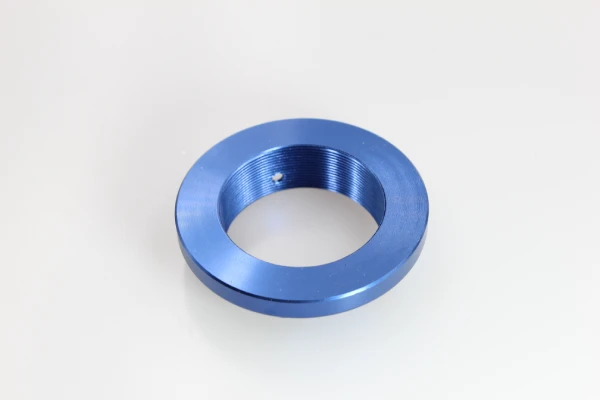
The quickest way to optimize precision CNC machining quotes is to eliminate uniform tolerances from non-critical geometric features. Engineering drawings typically default to a ±0.005” (±0.10 mm) tolerance applied uniformly to all surfaces via the title block. However, cost-effective CNC machining services rely on isolating functional features: strict tolerances should be applied only to mating interfaces, press-fit bearings, or dynamic alignment surfaces. Non-mating outer contours, clearance cavities, and aesthetic chamfers should default to standard commercial tolerances, such as ISO 2768-m (medium).
By clearly marking critical dimensions while leaving secondary features open, the purchaser can prevent machinists from performing unnecessary light finishing, constantly adjusting tool offsets, and conducting tedious in-process gauge checks during custom CNC machining. This distinction enables machining shops to maximize spindle feed rates and run longer, unattended batch machining operations, resulting in immediate and quantifiable reductions in unit costs for high-volume CNC machining projects.
Leveraging GD&T (Geometric Dimensioning and Tolerancing) Wisely
Traditional coordinate tolerancing often forces overly restrictive manufacturing boundaries, driving up CNC machining costs unnecessarily. Applying Geometric Dimensioning and Tolerancing (GD&T)—specifically True Position with Maximum Material Condition (MMC)—significantly increases process capability during precision CNC machining. MMC provides a “bonus tolerance” as feature sizes deviate from their smallest limit, allowing machine operators additional positioning leeway while guaranteeing functional assembly fit.
Furthermore, replacing tight linear tolerances on planar surfaces with Profile of a Surface or Flatness controls simplifies datum setups on multi-axis CNC machining centers. By communicating functional requirements through proper GD&T rather than tight linear coordinates, procurement engineers give suppliers the geometric flexibility needed to utilize standard modular fixtures, speed up part setup, lower scrap risk, and deliver substantially lower supplier quotes for complex CNC machining components.
Designing Within Standard Tool Sizes to Avoid Custom Tooling Costs
The geometry of a part directly determines the choice of cutting tools and the overall CNC machining cycle time. If the fillet radius of an internal cavity is designed to be smaller than the diameter of a standard end mill, the machining shop will be forced to use an undersized tool and reduce the feed rate, thereby significantly increasing milling time. To achieve efficient metal machining, the internal corner radius should be at least 115% to 150% of the tool radius. This allows the tool to rotate smoothly and prevents it from getting stuck in corners, which can cause chatter or tool breakage.
Furthermore, deep and narrow cavities with an aspect ratio (length-to-diameter ratio) greater than 4:1 can cause severe tool deflection during the CNC machining process. Machining such features requires specialized long-neck carbide end mills, low-speed point-milling cycles, or costly electrical discharge machining (EDM) processes. By matching internal fillet radii, slot widths, and groove depths to off-the-shelf imperial or metric tool sizes, design engineers can streamline the custom CNC machining process, avoid the additional costs of custom tools, and maximize metal removal rates.
Only 4 steps
online custom metal fabrication parts
Contact our experts team and experience the efficiency and economic benefits of digital metal fabrication services.
Upload Design Files
STL , STEP (.stp), IGES (.igs), (.ZIP), or PDF.
Also be a sample or an idea
Quote & Design Analysis
Instant factory quotes and DfM reports, the most reasonable solution.
Manufacturing Begins
Digital processes can initiate order tasks within 24 hours.
On-Time Delivery
Keeping delivery promises, approved by 3000+ Global Company buyers.
Material Behavior and Its Impact on Achieving Precision in CNC Machining Components
Material selection and post-processing largely determine the precision of the CNC machining process, as thermal expansion, residual stress relief, and surface coating deposition can all cause geometric deformation. Therefore, specialized strategies are required to maintain strict dimensional tolerances in a cost-effective manner.
Thermal Expansion and Residual Stress in Thin-Walled Components
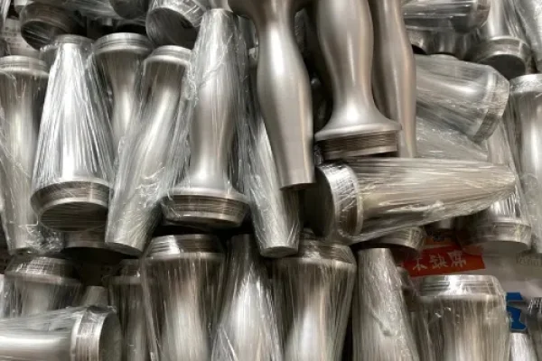
The behavior of materials during high-speed CNC machining largely determines the final dimensional stability. Raw materials such as 6061-T6 extruded aluminum or cold-rolled stainless steel contain internal residual stresses. During machining, as material is removed, these stresses become unbalanced, causing thin-walled features (thickness less than 1.5 mm) or long, flat plates to warp after being released from the fixture.
Furthermore, materials with a high coefficient of thermal expansion (CTE) expand during aggressive dry milling. If tight tolerances are measured while the workpiece is still hot on the machine, the dimensions will shrink beyond specification after cooling to room temperature.
To maintain tight tolerances while avoiding high scrap rates, manufacturers must perform multiple roughing passes and stress-relief heat treatment before final finishing—which significantly increases the cycle time of the overall CNC machining process.
Adjusting CNC Machining Tolerances Based on Post-Processing Operations
Failure to account for the thickness of surface treatment layers during initial drawing design is a common cause of costly quality rejections. Surface treatment processes such as Type II/Type III anodizing, electroless nickel plating, or powder coating can cause localized dimensional changes in the finished parts.
For example, Type III hard anodizing penetrates the metal substrate and can increase the surface layer thickness by up to 0.025 mm (0.001″) on each side. If engineering drawings are based solely on pre-plating CNC machining dimensions and specify strict pinhole or thread tolerances, interference issues will arise during final assembly.
Machining shops must compensate for this by pre-machining feature boundaries within strict dimensional limits to account for the increase in coating thickness. Purchasers should clearly specify whether drawing tolerances apply before or after surface treatment to avoid unnecessary rework, custom chasing taps, or costly batch scraps in precision CNC machining projects.
Collaborating with Precision CNC Machining Manufacturers
Engaging in technical collaboration with experienced CNC machining suppliers as early as the request for quotation (RFQ) stage helps resolve issues with suboptimal drawing tolerances, streamlines the manufacturing workflow, and reduces the risk of scrap before production begins—thereby significantly lowering the overall bill of materials (BOM) cost for parts.
Communicating Fit, Form, and Function Early in the RFQ Stage
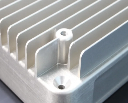
Clearly communicating the assembly context of parts during the request for quotation (RFQ) stage can prevent unnecessary manufacturing costs. Providing native 3D CAD models alongside 2D drawings enables custom CNC machining suppliers to evaluate actual functional fit interfaces. When a machining shop’s estimator understands whether a feature is intended as an aesthetic shell edge or as a high-load, pressure-bearing journal, they can propose adjustments to meet the target tolerances.
For example, using fit grades (such as ISO fit designations H7/g6) instead of strict linear dimensions provides suppliers with flexibility when selecting cutting strategies. Early involvement enables engineers to identify excessively wide tolerances specified in drawings, align target manufacturing tolerances directly with functional fit requirements, and prevent suppliers from adding risk premiums to their initial precision CNC machining quotes.
Requesting a DFM Review Prior to Production Sign-Off
Conducting a rigorous Design for Manufacturability (DFM) review before final approval is the ultimate safeguard against cost overruns. Experienced CNC machining suppliers evaluate part geometries based on the capabilities of the shop’s machine tools, tool reach limitations, and fixture clamping points. Professional DFM feedback can highlight hidden cost drivers, such as deep internal fillets that require specialized long-reach cutting tools, or thin-walled sections prone to chatter during milling.
By reviewing proposed tolerance adjustments prior to metal CNC machining, procurement teams can update engineering drawings to enable the use of standard cutting tools and streamline inspection processes. Collaborating with skilled manufacturers on pre-production DFM analysis reduces engineering change orders (ECOs), shortens lead times, and ensures predictable quality across every production batch.
Conclusion: Striking a Balance Between Engineering Performance and Manufacturing Efficiency
A cost-effective CNC machining service does not mean lowering quality standards, but rather eliminating unnecessary geometric precision requirements. Every dimension specified on an engineering drawing directly affects spindle runtime, cutting tool selection, and the indirect costs of quality control.
By distinguishing between critical fit features and commercial tolerance ranges, and by making judicious use of Geometric Dimensioning and Tolerancing (GD&T), procurement and engineering teams can proactively eliminate hidden drivers of manufacturing costs. Early collaboration with experienced contract manufacturers during the Request for Quote (RFQ) phase ensures that part designs align with the actual capabilities of the CNC machining shop.
Ultimately, by optimizing tolerances, it is possible to harmonize mechanical performance with maximum manufacturing efficiency, deliver high-precision CNC-machined components, and ensure the project’s profitability.