

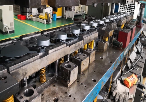
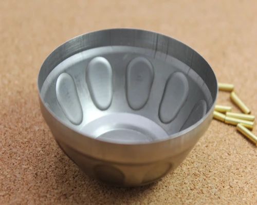
In precision CNC machining, Design for Manufacturability (DFM) serves as the technical bridge connecting nominal CAD geometry to actual machining on the shop floor. For procurement managers and mechanical design engineers in North America, feeding unoptimized CAD models directly into the contract manufacturing process poses multiple operational risks: excessive tool wear, unnecessary multi-axis setups, unbudgeted scrap rates, and extended Request for Quote (RFQ) processing cycles.
As an established precision CNC machining manufacturer, Supro MFG conducts rigorous engineering DFM reviews before the spindle is even started. Evaluating structural features from a production perspective ensures that specified tolerances, wall thicknesses, and internal groove geometries align directly with the limits of standard subtractive machining. Optimizing internal radii, deep-hole length-to-diameter ratios, and reference face alignment can significantly reduce hourly machining costs while maintaining mechanical strength.
Adhering to standardized CNC machining DFM protocols eliminates structural design flaws before chips are even formed, enabling rapid prototyping turnaround and a seamless transition to high-volume production. Implementing this technical checklist ensures your custom parts achieve rated engineering performance while delivering optimal unit economics.
Structural Geometry and Wall Thickness Guidelines in the CNC Machining Process
In precision CNC machining, structural geometry determines static stiffness and cutting dynamics. Deviations from recommended aspect ratios can lead to severe tool deflection, workpiece chatter, and thermal deformation in thin-walled parts. This directly affects final dimensional stability and results in increased scrap rates during production.
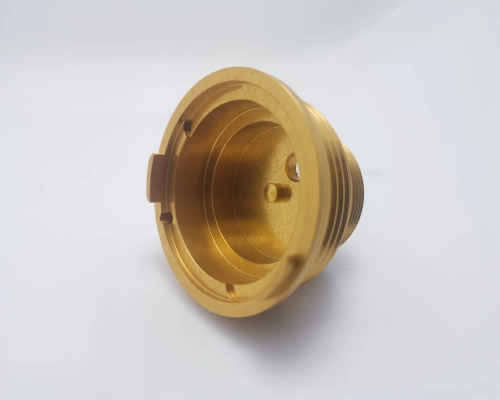
Minimum Wall Thickness Thresholds Across Alloys
In custom CNC machining, maintaining the integrity of structural walls directly prevents yield failure and dynamic displacement of the workpiece under mechanical cutting loads. When machining thin-walled aluminum alloys (such as AL 6061-T6 or 7075-T6), the wall thickness must meet a minimum threshold of 0.8 millimeters (0.032 inches) to prevent permanent deflection, structural tearing, or thermal deformation.
For austenitic stainless steel (SUS 304/316) and high-toughness alloy steel, the minimum wall thickness must be increased to 1.5 millimeters (0.060 inches) due to increased cutting forces, severe strain hardening, and high heat concentration near the cutting edge.
In subtractive CNC machining processes, the machining of non-standard thin-walled structures requires low feed rates, shallow cutting depths, and custom vibration-damping fixtures, which directly increase machine cycle times and unit procurement costs. Standardizing wall thickness specifications to the structural limits of specific materials ensures strict control of feature tolerances, eliminates part warping, and guarantees efficient high-volume production.
Mitigating Part Deformation and Chatter
During high-speed CNC machining of tall, unsupported wall structures, vibration, chatter, and workpiece deflection are major quality bottlenecks. A high depth-to-thickness ratio (greater than 10:1) can trigger dynamic resonance under radial cutting forces, resulting in unacceptable tool chatter marks, microcracks, and surface profiles that exceed tolerance limits.
To mitigate self-excited chatter during the CNC machining process, mechanical design engineers should incorporate structural stiffeners, transverse ribs, or tapered wall profiles at the base of vertical geometries. Stiffeners can increase the structural moment of inertia without significantly adding material weight, allowing the tool to operate at optimal feed rates without inducing harmonic vibrations.
Additionally, maintaining a large internal transition radius at the bottom of the wall reduces stress concentration and prevents tool jamming. Designing self-supporting geometries eliminates the need for expensive custom anti-vibration fixtures, thereby ensuring surface integrity and optimizing manufacturing throughput in industrial procurement processes.
Internal Features of CNC Machining Components: Pocket Depths, Radii, and Tool Access
In precision CNC machining, internal geometry directly determines the selection of cutting tools, spindle load, and the efficiency of toolpaths. If the depth-to-width ratio of a pocket is not optimized and sharp internal angles are present, it can result in excessive tool overhang, leading to chatter, reduced feed rates, and catastrophic damage to end mills.

Optimizing Internal Corner Radii for Standard Milling Cutters
In custom CNC machining, vertical fillets at internal corners must be slightly larger than the radius of a standard end mill to prevent tool chatter and breakage. Designing 90-degree right angles forces 3-axis CNC machining centers to halt feed, resulting in severe corner dwell marks, excessive radial cutting, and premature tool wear.
Engineers should specify an internal fillet radius that is at least 10% larger than the tool’s nominal radius (for example, specify a 3.5-millimeter fillet radius for a 6-millimeter end mill). This ensures that the toolpath moves smoothly along continuous arc vectors without scratching the pocket walls. When square-fit parts must structurally have sharp internal square corners, implementing corner relief cuts such as “dog-bone” or “T-bone” fillets enables standard round end mills to clear the required corner envelope without expensive EDM processing or custom tooling.
Depth-to-Width Limitations for Deep Cavities
In high-speed CNC machining, the geometry of the cavity determines tool rigidity, deflection limits, and chip evacuation efficiency. When the cavity depth exceeds four times the tool diameter, the deflection of a long-shank end mill increases exponentially, forcing operators to significantly reduce spindle speed and feed rate.
In subtractive CNC machining, deep and narrow pockets lead to chip buildup, heat accumulation, and a significantly increased risk of catastrophic tool breakage, thereby substantially extending machine cycle times and driving up hourly machining costs. To optimize design for manufacturability (DFM), mechanical designers should limit pocket depth to no more than three times the tool diameter whenever possible, or design stepped pocket walls to maintain optimal shank stiffness.
For deep enclosure geometries, widening pocket access or breaking down deep monolithic structures into modular, multi-piece assemblies eliminates the need for extended tool reach, preserving tight dimensional tolerances while lowering overall unit manufacturing costs for procurement managers.
Hole and Thread Specifications for CNC Machining Components
Custom CNC machining requires precise hole and thread designs to maintain structural integrity and prevent tool failure. Unoptimized depth-to-diameter ratios or excessive thread engagement can lead to drill deflection, chip buildup, tap breakage, and unexpected tool wear during production.
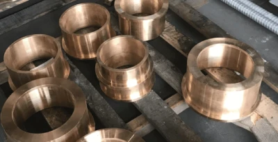
Hole Depth-to-Diameter Ratios for Standard Drills
In precision CNC machining, maintaining standard hole depth-to-diameter ratios is critical for preventing drill deviation, heat buildup, and premature tool failure. Standard twist drills operate efficiently when the hole depth does not exceed 4 to 6 times the drill diameter.
When the depth-to-diameter ratio exceeds 6:1, high-speed CNC machining centers require the use of spot-drilling cycles, specialized gun drills, or high-pressure coolant within the spindle to clear chips from deep holes. Deep, narrow holes significantly increase the risk of tool deflection and radial runout, often resulting in off-axis holes or complete drill breakage.
For internal tapped blind holes, mechanical engineers should specify a 118° or 135° rake angle at the bottom of the drill bit to accommodate standard cutting edges. Limiting the hole design to the standard drilling depth range not only avoids the cost of custom long-shank tools but also shortens machine cycle times and ensures strict control of hole position tolerances throughout the entire production batch.
Internal and External Thread Engineering
Thread integrity in precision CNC machining depends directly on proper tap clearance, chamfer design, and realistic thread engagement lengths.
A common design pitfall in CNC machining process is specifying thread depth beyond 2x the nominal thread diameter; engineering data demonstrates that over 90% of structural holding strength is achieved within the first 1.5x to 2x diameter engagement. Excessive thread depth yields minimal mechanical benefit while exponentially increasing tap breakage risks, especially in tough stainless steels or titanium alloys.
For internal tapped blind holes, engineers must include unthreaded pilot relief at the bottom (at least 0.5x diameter) to allow chip clearance for taps. For external threads, providing a 45° lead-in chamfer ensures smooth thread engagement and protects lead threads during handling. Standardizing thread limits prevents broken taps inside finished components and streamlines automated tapping cycles for procurement teams.
Only 4 steps
online custom metal fabrication parts
Contact our experts team and experience the efficiency and economic benefits of digital metal fabrication services.
Upload Design Files
STL , STEP (.stp), IGES (.igs), (.ZIP), or PDF.
Also be a sample or an idea
Quote & Design Analysis
Instant factory quotes and DfM reports, the most reasonable solution.
Manufacturing Begins
Digital processes can initiate order tasks within 24 hours.
On-Time Delivery
Keeping delivery promises, approved by 3000+ Global Company buyers.
CNC Machining Tolerances, Geometric Dimensioning and Tolerancing (GD&T), and Surface Roughness Requirements
Tolerance accumulation, the application of Geometric Dimensioning and Tolerancing (GD&T), and surface roughness targets directly determine process capability (Cpk) and operating costs in precision CNC machining. Over-specifying non-critical dimensions increases secondary grinding, inspection costs, and total unit procurement costs without providing any practical mechanical functional benefits.
Tight Tolerances vs. Standard Machining Classifications
In custom CNC machining, setting excessively tight tolerances for non-critical features results in unnecessary cost increases and extended lead times. Standard CNC machining process capability can reliably achieve ISO 2768-m (medium) tolerance grades (±0.1 mm to ±0.2 mm) without the need for specialized cutting tools, secondary grinding, or temperature-controlled inspection laboratories.
Applying ultra-tight tolerances (such as ±0.005 mm or ISO 2768-f) to non-fit dimensions will severely limit feed rates, increase machine calibration cycles, and lead to higher scrap rates. Mechanical design engineers should identify “Critical to Quality” (CTQ) functional surfaces—such as bearing bores or locating pin holes—separately and apply standard commercial tolerances to other areas.
Proper application of Geometric Dimensioning and Tolerancing (GD&T) in accordance with the ASME Y14.5 standard establishes a clear reference system without over-constraining the part. Separating true fit from functional tolerances optimizes process capability (Cpk) and maintains cost-effectiveness per unit in high-volume CNC machining contract manufacturing.
Tolerance Class | ISO 2768 Grade | Typical Dimensional Tolerance | Relative Machining Cost Multiplier | Required Manufacturing Process & Quality Control |
Commercial / Standard | ISO 2768-m (Medium) | ±0.10 mm to ±0.20 mm (±0.004″ to ±0.008″) | 1.0x (Baseline) | Standard 3-Axis CNC machining; standard feed rates; batch CMM or manual caliper inspection. |
Fine / Precision | ISO 2768-f (Fine) | ±0.05 mm to ±0.10 mm (±0.002″ to ±0.004″) | 1.3x – 1.5x | High-precision 3-axis / 5-axis CNC machining; reduced feeds & speeds; temperature-monitored shop floor; 100% feature CMM verification. |
Ultra-Precision (CTQ) | Customized Specification | ±0.005 mm to ±0.025 mm (±0.0002″ to ±0.0010″) | 2.5x – 4.0x+ | Specialized finish passes, jig boring, surface grinding, or wire EDM; strict thermal stabilization (20°C laboratory); mandatory Cpk ≥ 1.33 statistical process control. |
Surface Roughness (Ra) Specifications for CNC-Machined Components and the Impact of Post-Processing
In subtractive CNC machining processes, surface roughness requirements directly influence machining cycle times, cutting parameters, and secondary finishing operations. Standard post-machining surface roughness typically ranges from Ra 3.2 µm to Ra 1.6 µm (125–63 µin) and can be successfully achieved in the initial CNC machining operation without the need for secondary polishing.
Stringent ultra-fine surface specifications (such as Ra 0.8 µm or Ra 0.4 µm) require low feed rates, micro-stepping toolpaths, and secondary grinding processes, which significantly increase the cost per hour of machining.
Furthermore, mechanical engineers must account for dimensional changes during post-processing when initially planning custom CNC machining solutions; anodizing, electropolishing, or thick powder coating can affect dimensions with tight tolerances by altering the thickness of the final surface layer. Setting functional Ra targets based on dynamic sealing or bearing requirements—rather than aesthetic preferences—ensures both cost-effective manufacturing and the maintenance of strict dimensional accuracy after surface treatment.
Setup Reduction and Multi-Axis CNC Machining Considerations
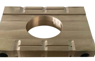
In precision CNC machining, minimizing adjustments to clamping orientation and fully utilizing multi-axis kinematics directly improves production efficiency. Aligning geometric features to a unified reference plane reduces cumulative fixture errors, eliminates the need for manual repositioning, and lowers the hourly machine rate during high-volume production runs.
Designing for Single-Setup or Minimal Flip Operations
In custom CNC machining, reducing the total number of fixture positioning operations is critical for eliminating cumulative clamping errors and controlling labor costs in the machining shop. Designing component features that align along a single primary Cartesian plane allows high-speed CNC machining centers to complete milling, drilling, and profiling in a single continuous operation.
In traditional CNC machining processes, each manual flipping of the workpiece requires re-clamping, soft chucks, and recalibration of the reference plane, which inherently introduces the risk of tolerance accumulation and increases the scrap rate. Mechanical engineers should standardize internal features so they can be machined using a top-down primary tool vector and establish clear, easy-to-clamp reference planes for use with vise clamping.
Eliminating multi-sided repositioning in precision CNC machining not only shortens production cycles and simplifies quality assurance workflows but also directly reduces unit procurement costs for engineering teams and procurement managers.
3-Axis vs. 5-Axis CNC Machining Feasibility
Evaluating part geometry against 3-axis and 5-axis CNC machining capabilities determines both manufacturing lead times and overall tooling investments.
While standard 3-axis CNC machining offers lower hourly spindle rates, highly complex geometries with compound angles or undercut profiles may require multiple fixture setups that erode cost efficiency. Conversely, 5-axis CNC machining provides continuous multi-axis tool access, allowing complex sculpted impellers or angled aerospace brackets to be machined in a single setup with shorter, stiffer cutters. However, 5-axis CNC machining carries significantly higher machine hour rates and programming overhead.
Design engineers should simplify complex single-piece housings into modular sub-assemblies suitable for 3-axis CNC machining unless 5-axis kinematic access is mandatory for tight geometric tolerances, ensuring optimized production economics for contract manufacturing programs.
Looking for a reliable custom sheet metal fabrication companies?
Talk To Supro MFG Expert Team
Contact us for competitive ex-factory prices,
and a full range of technical support services.
Materials Selection and Tool Clearance Guidelines in CNC Machining
In the CNC machining process, material selection and tool clearance directly determine machinability ratings, spindle load, and toolpath accessibility. Selecting standard-sized blanks and avoiding restrictive undercut geometries eliminates the additional costs associated with custom tools while preventing spindle interference.
Machinability Index Ratings for Common Industrial Alloys
In high-precision CNC machining, selecting alloys with higher machinability ratings directly impacts cutting speed, tool life, and total cost per unit.
Material selection determines spindle power requirements and chip-breaking dynamics during subtractive manufacturing processes. For example, the easily machinable aluminum alloy AL 6061-T6 serves as an industry benchmark, offering high cutting speeds and extremely low tool wear; in contrast, austenitic stainless steels (such as SUS 304/316) exhibit significant work hardening and low thermal conductivity, which substantially reduce feed rates in precision CNC machining.
Superalloys or quenched tool steels, on the other hand, require high-quality carbide cutting tools and high-pressure coolant strategies, thereby driving up hourly production costs. Matching mechanical strength requirements with material blanks that offer high machinability—and designing part dimensions to conform to standard off-the-shelf sheet and bar stock specifications—can eliminate unnecessary end-machining operations and ensure strict cost targets are met in contract CNC machining projects.
Tool Clearance and Approach Vector Verification
Tool accessibility and approach vector clearance dictate physical feasibility during 3-axis and multi-axis CNC machining. Designing undercut features, steep internal overhangs, or narrow clearance slots forces contract manufacturers to utilize specialized lollipop cutters, disc mills, or custom right-angle attachments, introducing severe vibration and tool deflection risks during CNC machining process.
Mechanical design engineers must verify spindle housing clearance and maintain unimpeded linear access along primary Cartesian axes. Designing generous draft angles on deep side-wall profiles and providing adequate tool entry relief allows standard end mills to operate at optimal cutting parameters during high-speed CNC machining. Eliminating restricted tool paths avoids custom tooling setup fees, reduces cycle times, and guarantees robust geometric accuracy during automated manufacturing operations for procurement and sourcing teams.
Conclusion
Implementing a comprehensive Design for Manufacturability (DFM) process before submitting a Request for Quote (RFQ) can transform nominal CAD drawings into cost-effective production realities. Conducting DFM validation early in the custom CNC machining process allows for the identification of structural bottlenecks—such as non-standard internal fillets, excessive wall thickness-to-width ratios, and overly restrictive tolerances—before raw materials are consumed or machine time is expended.
Partnering with a specialized CNC machining manufacturer ensures that every feature is directly aligned with three-axis and multi-axis subtractive machining capabilities. Standardizing features to commercially available tool specifications and optimizing reference plane layouts can significantly reduce machine hourly rates, avoid costly engineering change orders (ECOs), and ensure high Cpk process capability.
Implementing this CNC machining technical checklist can streamline procurement workflows, reduce scrap rates, and shorten the time-to-market from prototype to mass production for engineering managers and procurement specialists worldwide.
Supro is a CNC machining manufacturer based in China, equipped with 80 3-axis, 4-axis, and 5-axis CNC machines. We offer over 120 types of metal and plastic materials, and all production processes are completed in-house. We provide professional CNC machining services and online technical support. Whether you need rapid prototyping or batch production of metal and plastic parts, we can offer you a one-stop manufacturing solution! For technical inquiries or to discuss OEM partnerships, please contact our engineering team.