
In precision sheet metal bending, specifying an inner radius that is too small remains the primary cause of microcracks and catastrophic tensile failure of the outer layer. Failing to consider the material’s strain limit when designing components often turns a routine production process into a quality nightmare with an unacceptably high scrap rate. To master sheet metal bending technology, one must have a clear and mathematically rigorous understanding of the minimum bending radii for various alloy compositions and temper conditions.
During the sheet metal bending process, the material experiences simultaneous tensile stress on the outer layer and compressive stress on the inner layer along the neutral axis. When the alloy is pushed beyond its threshold limit for tensile elongation, plastic deformation transitions into fracture.
This engineering guide provides a detailed analysis of the physical and mechanical principles that determine the selection of the minimum sheet metal bending radius. By aligning your Design for Manufacturability (DFM) protocols with validated metallurgical metrics—including grain anisotropy, work hardening, and die geometry—designers can eliminate the risk of cracking, ensure tight dimensional tolerances, and optimize the cost-effectiveness of scalable manufacturing.
The Metallurgy of Sheet Metal Bending: Why Do Parts Crack?
Structural cracking occurs during the custom sheet metal bending process when localized tensile strain exceeds the material’s true fracture ductility, which triggers the coalescence of microvoids along localized shear bands during plastic deformation.
Tension on the Outer Fiber vs. Compression on the Inner Fiber
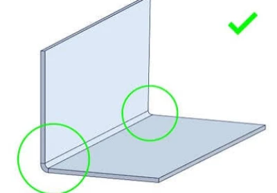
In any sheet metal bending process, a steep stress gradient develops across the material cross-section. The inner radius is subjected to severe compressive stress, causing localized material thickening, while the outer radius is subjected to extreme tensile strain. These two opposing stress fields are separated by the neutral axis, which shifts toward the inner bending radius as plastic deformation progresses. When the outer radius becomes steeper, the tensile strain experienced by the outermost fibers increases exponentially.
If this localized strain exceeds the material’s fracture strain threshold, necking occurs on the outer metal surface, immediately followed by the formation of microcracks. Controlling the inner radius ensures that the elongation of the outer fibers is safely maintained within permissible physical limits.
Material Grain Orientation (Anisotropy) and Sheet Metal Bending Direction
Mechanical rolling introduces structural anisotropy, elongating the metal’s grain structure along the rolling direction. During precision sheet metal bending, the angle between the bend line and the longitudinal grain orientation largely determines the resistance to cracking.
Bending parallel to the grain orientation concentrates tensile stress at existing grain boundaries, significantly increasing the risk of longitudinal cracking along the bend ridge. Conversely, sheet metal bending perpendicular to the grain direction distributes tensile stress across multiple grain boundaries, thereby maximizing fracture resistance.
When multi-axis bending cannot achieve the optimal orientation, setting the bend line at a 45-degree angle to the rolling direction provides a balanced metallurgical compromise for small-radius geometries.
Ductility, Work Hardening, and Elongation Limit
A material’s ultimate ability to resist cracking during custom sheet metal bending depends on its uniform elongation and strain hardening index (n-value). As plastic strain accumulates along the outer bending radius, the dislocation density within the crystal lattice rises rapidly, leading to work hardening. Although work hardening increases local yield strength, it also significantly reduces residual ductility.
High-strength alloys or materials in a high-hardness condition—such as 6061-T6 aluminum alloy—have low strain hardening capacity, and their ductility thresholds are limited. Once the local tensile strain exceeds the material’s total ductility limit, dislocation motion ceases, leading to stress concentration, which ultimately triggers the coalescence of brittle microcracks and results in immediate surface tearing.
Understanding the Minimum Sheet Metal Bending Radius Rule
The minimum bending radius rule standardizes the geometric thresholds for maintaining the tensile elongation of outer-layer fibers within the permissible material strain limits during the sheet metal bending process; this threshold is directly calibrated as a multiple of the blank thickness (1t, 2t, or 3t).
Defining Material Thickness (t) as a Reference Parameter
In precision sheet metal bending, expressing the inner bend radius (R) as a direct multiple of the material thickness (t) establishes a dimensionless geometric reference. As sheet thickness increases, the total strain experienced by the outer edge during the sheet metal bending process increases exponentially for any given inner bending radius. Standardizing bending radius rules to 1t, 2t, or 3t ensures that, regardless of nominal thickness, the elongation of the outer edge fibers always remains below the material’s critical fracture strain threshold.
For precision sheet metal bending operations, determining the minimum bending radius based on blank thickness also enables process engineers to accurately predict the selection of punch tip radius and variations in the K-factor, thereby stabilizing the position of the neutral axis across different production batches.
Standard Benchmark Ratios Across Common Engineering Alloys
Selecting an appropriate bending ratio requires balancing the alloy’s ductility and yield strength based on target formability metrics. Highly ductile alloys, such as 5052-O aluminum alloy or cold-rolled low-carbon steel, can easily achieve a compact bending radius of 1t on standard sheet metal bending equipment. However, high-strength materials require significantly larger geometric thresholds to prevent a decline in structural performance.
Due to rapid work hardening, stainless steels (such as 304 or 316) typically require a minimum sheet metal bending radius of 1.5t to 2t; whereas the structural aluminum alloy 6061-T6 requires a radius of 3t to 4t to prevent cracking on the outer surface. The benchmark reference table below outlines the standard manufacturing tolerances for common engineering materials:
Material Grade | Temper / State | Recommended Min. Bend Radius (R) | Tensile Elongation Threshold |
Cold Rolled Steel (CRS) | Commercial Quality | 1.0t | ~20% – 30% |
Stainless Steel 304 | Annealed | 1.5t – 2.0t | ~40% – 55% |
H32 (Quarter Hard) | 1.5t | ~12% – 18% | |
Aluminum 6061 | T6 (Heat Treated) | 3.0t – 4.0t | ~8% – 10% |
Why “Sharp Bends” (R=0) Fail in Production
In modern sheet metal bending processes, it is physically impossible to set a zero-radius or “sharp-angle” inside bend. When the tip radius of the upper punch is smaller than the material’s natural minimum radius, the die cannot form a smooth geometric arc; instead, it pierces the blank like a chisel.
This localized chiseling creates severe stress concentration notches along the inner bend line while forcing the outer fibers beyond their ultimate tensile strain limit. The resulting mechanical indentations severely compromise the structural integrity of sheet metal bending components, triggering immediate microcracks that propagate into full structural fractures under operational loads.
Only 4 steps
online custom metal fabrication parts
Contact our experts team and experience the efficiency and economic benefits of digital metal fabrication services.
Upload Design Files
STL , STEP (.stp), IGES (.igs), (.ZIP), or PDF.
Also be a sample or an idea
Quote & Design Analysis
Instant factory quotes and DfM reports, the most reasonable solution.
Manufacturing Begins
Digital processes can initiate order tasks within 24 hours.
On-Time Delivery
Keeping delivery promises, approved by 3000+ Global Company buyers.
Sheet Metal Bending Guidelines for Different Materials: Soft and Hard Conditions
The condition of the material determines its yield-to-tensile strength ratio and plastic strain envelope during the sheet metal bending process; therefore, hard-condition (precipitation-hardened) alloys require a larger minimum bending radius compared to soft-condition (strain-softened) alloys.
Carbon Steel and Stainless Steel Grades
The formability of steel alloys varies significantly due to carbon equivalent and strain-hardening behavior during the custom sheet metal bending process. Commercial low-carbon steels (such as A36 or 1008) have a high plastic strain limit and can reliably be formed to a tight bending radius of 1t. In contrast, austenitic stainless steels (grades 304 and 316) undergo rapid work hardening as the dislocation density increases sharply along the outer bending radius.
This rapid strain hardening increases the local yield strength while depleting the remaining ductility, thus requiring a conservative minimum sheet metal bending radius of 1.5t to 2.0t.
High-strength low-alloy (HSLA) steels require larger geometric allowances (up to 3t) to prevent immediate tensile splitting. Process engineers must also anticipate that high-strength steel will exhibit significant springback; therefore, flange corners must be overbent to ensure accuracy in final dimensional tolerances across different production batches.
Aluminum Alloys: Navigating the Trap Between 5052 and 6061
In precision sheet metal bending, choosing between 5052 and 6061 aluminum alloys is a critical Design for Manufacturing (DFM) decision. The non-heat-treatable 5052-H32, which is magnesium-solid-solution-strengthened, maintains excellent strain-hardening capabilities while allowing sharp bend radii of 1.0t to 1.5t without cracking.
In contrast, the age-hardened 6061-T6 contains magnesium silicide (Mg₂Si) intermetallic precipitates, which restrict dislocation mobility. When performing custom sheet metal bending, 6061-T6 has a narrow yield-to-tensile strength margin; attempting bend radii smaller than 3t to 4t typically results in catastrophic tear-out at the grain boundaries.
When structural requirements call for both the strength of 6061 and complex bending radius geometries, designers must specify the annealed O-temper for forming, followed by solution heat treatment and artificial aging to restore T6-temper properties after sheet metal bending.
Copper, Brass, and Special Alloys
In high-precision sheet metal bending applications, such as busbars and electrical cabinets, non-ferrous metals—including copper and brass alloys—exhibit unique plastic deformation characteristics. Pure oxygen-free copper (C10200/C11000) in a soft-annealed condition has an excellent elongation threshold, allowing it to be easily formed into inner radii ranging from 0.5t to 1t without developing microcracks.
However, cold-worked semi-hard or hard materials exhibit accelerated work hardening rates; therefore, to prevent edge embrittlement, the minimum sheet metal bending radius must be increased to 1.5t or higher.
Brass (C26000) strikes a balance between high tensile strength and moderate formability; however, when performing custom sheet metal bending along its rolling direction, a larger bending radius is required to avoid longitudinal fractures. For beryllium copper and specialty spring alloys, specifying a pre-forming annealing cycle remains critical before performing complex multi-axis forming operations.
DFM Best Practices for Sheet Metal Bending to Eliminate Cracking
Implementing sound DFM (Design for Manufacturability) practices in the sheet metal bending process can eliminate localized stress concentrations by employing strategic bending relief geometries, calibrating the V-die opening ratio of the press brake, and addressing micro-defects on edges prior to precision cold forming.
Relief Notches and Tear Drops for Flange Corners
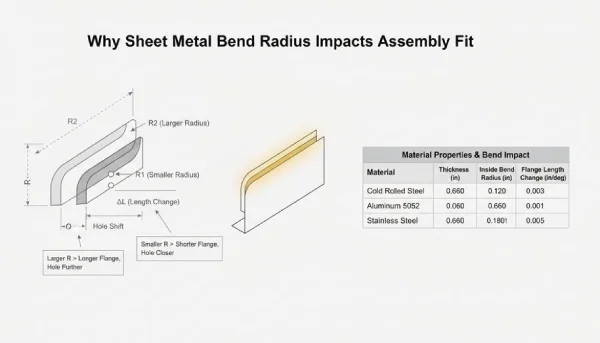
If appropriate relief notches are not provided when bending flanges of partial width, severe material tearing can occur at the transition point between the bent metal and the unformed material. During the precision sheet metal bending process, localized lateral strain pulls on adjacent unbent material, resulting in complex multi-axial stress concentrations whose values can exceed the alloy’s ultimate shear strength.
By incorporating rectangular or teardrop-shaped bending relief notches, plastic deformation can be strictly confined to the bending zone. To ensure the structural integrity of sheet metal bending components, DFM standards mandate that the relief notch depth must extend past the tangent line of the bend radius by at least 1.0t, while the relief width should equal or exceed the material thickness (t ≥ 1.5 mm).
For high-stress structural enclosures, specifying a smooth, circular teardrop-shaped notch effectively dissipates stress concentrations, thereby eliminating microcracks that form at the junction along the flange root.
V-Die Selection and Tooling Calibration
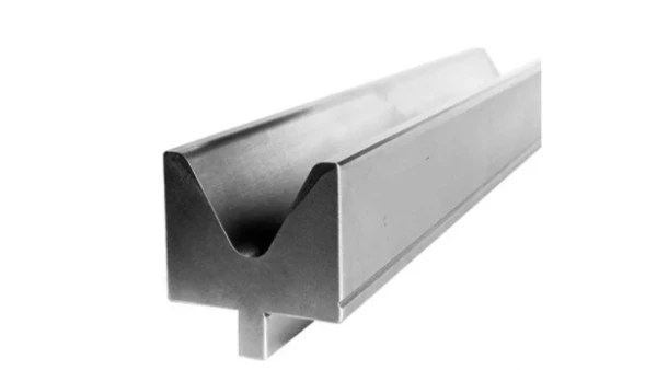
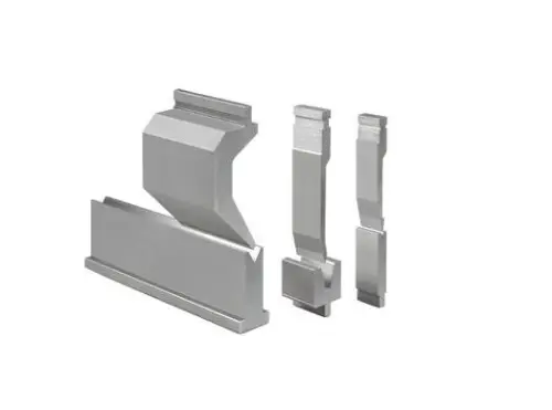
In the air sheet metal bending process, the geometry of the tooling determines the actual forming radius. Matching the width of the lower V-die opening (V) to the material thickness (t) directly determines the internal strain distribution and forming force. Sheet metal bending manufacturers typically use an 8t V-die opening (V = 8t) for standard-thickness materials, resulting in a natural inner radius approximately equal to 15% to 16% of the die width.
Forcing thick or low-ductility stock into an undersized V-die (V < 6t) drastically sharpens the inner radius, forcing the punch tip to penetrate the neutral axis and causing severe tensile gouging of the outer skin. Conversely, selecting a calibrated 10t to 12t V-die opening reduces the total tonnage requirement, alleviates tensile stress on the outer layer fibers, and prevents catastrophic fractures in high-strength aluminum and stainless steel components.
Laser Cutting Edge Quality and Burr Removal
Edge preparation prior to cold forming plays a decisive role in preventing structural failure during high-precision sheet metal bending. Hot laser cutting produces microcracks, slag, and a brittle heat-affected zone (HAZ) along the cut contour, while mechanical punching can leave sharp edge burrs. During custom sheet metal bending, these microscopic defects become severe stress concentration points that rapidly propagate into macroscopic cracks along the outer stretch radius when subjected to stress.
Implementing deburring, edge finishing, or vibratory tumbling can effectively remove microcracks and smooth the edge geometry. Furthermore, orientation plays a vital role: ensuring that punch burrs face inward toward the compressive bend zone—rather than outward along the tensile face—drastically reduces the risk of tensile crack propagation during mass production runs.
Looking for a reliable custom sheet metal fabrication companies?
Talk To Supro MFG Expert Team
Contact us for competitive ex-factory prices,
and a full range of technical support services.
Conclusion & Supro MFG Engineering Support
To eliminate structural fractures in sheet metal bending, a balance must be achieved among CAD geometry, alloy ductility, and the physical characteristics of the bending die. An overly simplistic approach to selecting the minimum sheet metal bending radius often leads to a surge in scrap rates, die wear, and unforeseen failures on the shop floor.
By standardizing design practices around validated material elongation thresholds, anisotropic grain orientation, and calibrated V-die opening ratios, design engineers can ensure high-yield production for both structural brackets and complex, precision enclosures.
Supro is an experienced sheet metal bending manufacturer; our application engineering team bridges the gap between digital DFM modeling and actual manufacturing execution. We utilize advanced multi-axis CNC press brakes equipped with adaptive bend angle sensors to evaluate your part geometry prior to production, optimizing bend radii, preventing stress concentrations, and optimizing material selection.
Whether you’re transitioning high-precision prototypes to mass production or launching full-scale OEM manufacturing, contact Supro MFG today to leverage our advanced sheet metal bending technology and ensure zero-defect manufacturing.