

The sheet metal bending radius is far more than just a default CAD parameter; it is a core factor in cost control, structural integrity, and assembly accuracy. Although most designers default to the theoretical minimum of “1 times the thickness,” this often conflicts with actual economic realities on the shop floor—approximately 95% of parts with a thickness of 0.125 inches or less are formed using a standard 0.030-inch bending radius to avoid frequent die changes.
Excessively small bending radii can cause material cracking and unpredictable springback, particularly in high-strength materials such as stainless steel or 6061-T6 aluminum. Conversely, overly large or inconsistent radii can compromise K-factor calculations, leading to distorted flat patterns and costly tolerance stacking during multi-component assemblies.
At Supro Mfg, we analyze and optimize this variable—from V-die openings to material grain orientation—to minimize waste and ensure mating features align precisely without secondary machining. This article provides an in-depth analysis of how to master sheet metal bend radii—from the K-factor to die selection—to ensure your designs translate into high-quality, ready-to-assemble parts.
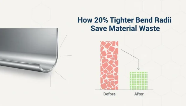
How 20% Tighter Bend Radii Reduce Material Waste
When the bend radius, bend allowance, and sheet metal thickness are precisely matched, material waste is significantly reduced. By reducing the sheet metal bend radius by 20%, the required flat blank size for parts can be effectively minimized. This direct reduction in blank size means that more parts can be produced from each sheet of material, resulting in less waste. The key is that this method relies on precise adjustment of the K-factor to maintain the final part’s accuracy, ensuring material savings without compromising tolerance requirements.
Matching Material Thickness with the Minimum Bending Radius
Balancing material thickness with the minimum bending radius can effectively prevent cracking and consistently reduce scrap. Since the optimal balance point differs between thin and thick sheets, the sheet metal bending radius should not be estimated based on experience alone.
Thin Sheet Strategy: Verify sheet metal specifications and confirm tensile strength and grain orientation. Set the minimum bending radius slightly above the material’s limit. Validate through test bending before mass production.
Key Control Points for Thick Sheets: Match punch radius to thickness to avoid overly tight inside corners. Monitor press tonnage during forming. Inspect for micro-cracks along the edges.
Key inspection points for all sheet metal bending radius:
Compare material thickness with die radius
Align the bend line with the grain direction whenever possible
Recalculate blank dimensions after radius changes
At Supro, the team treats sheet metal bend radius planning as a form of cost control rather than a matter of guesswork. Precise control of smaller inner bend radii means fewer cracked parts and reduced scrap accumulation.
Reducing the inner bend radius when bending stainless steel
Working stainless steel feels tough because its material properties fight back. Springback is real. A reduced inside bend radius in the bending process needs tight control in press brake bending.
Start with tooling. A polished punch nose reduces galling. Then adjust bottoming pressure to lock in the sheet metal bend radius you want. Too loose, and the metal relaxes. Too tight, and you risk surface marks that lead to trimming waste.
1)Dial in the press brake
2)Fine-tune backgauge positioning
3)Measure actual inside bend radius after forming
Recent industry data backs this push for precision:
“Fabricators adopting tighter radius control and digital bend simulation in 2025 report measurable reductions in material waste and rework,” notes a 2025 outlook from Deloitte’s manufacturing analysis.
supro mfg applies simulation before steel hits the brake, keeping sheet metal bend radius consistent across batches. That consistency cuts flange re-trims and protects margins.
Optimizing K-Factor for Aluminum Alloy to Minimize Bend Deduction
With aluminum alloy, the neutral axis shifts fast, so k-factor optimization drives accurate bend deduction in sheet metal forming. A sloppy k value means oversized blanks and wasted strips.
To keep the metal bend radius and flat layout tight:
Material science review:Confirm alloy grade.Check temper condition.
Bending calculations:Input target inside bend radius.Adjust k-factor based on test coupons.
Production lock-in:Update CAM data.Standardize bend allowance per thickness
At Supro, we have established a comprehensive closed-loop process:
Test bend small samples.
Measure real bend radius sheet metal output.
Recalculate bend deduction.
Release to production.
When sheet metal bend radius, k-factor, and bend allowance align, aluminum jobs run clean. supro mfg keeps this loop tight, so offcut waste shrinks and every blank earns its keep.
Are you looking for reliable & cost-effective
China Sheet Metal Fabricators
More than 150,000 OEM metal fabrication products delivered to 5,000+ global buyers.
And benefit from it!
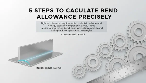
5 Steps to Calculate Bend Allowance Precisely
Accurate calculation of bend allowance begins with a critical variable: the sheet metal bend radius. This is not merely a mathematical calculation; this value directly determines the extent to which the neutral axis is stretched. If the bend radius is incorrect, precision flange components will fail to meet expectations. By systematically combining material properties and die selection with the target sheet metal bend radius, we eliminate guesswork and ensure that the flat pattern fully complies with the finished product’s specifications.
Step 1: Determine Sheet Metal Gauge and Relevant Mechanical Properties
When dialing in a sheet metal bend radius, material data drives everything. Start by identifying:Sheet Metal Gauge.Material Thickness.Tensile Strength.Yield Strength.Ductility
These values control how the sheet metal, bend zone stretches and compresses around the inside bend radius.
A tighter sheet metal bend radius increases strain. If ductility runs low, cracks show up fast. Shops like supro mfg typically log these numbers before calculating bend allowance to avoid guesswork.
Material Type | Thickness (mm) | Yield Strength (MPa) | Typical Min Bend Radius (×T) |
Stainless Steel 304 | 1.0 | 215 | 1.0T |
Galvanized Steel | 1.2 | 140 | 0.8T |
Aluminum 5052-H32 | 2.0 | 193 | 1.5T |
Mild Steel A36 | 3.0 | 250 | 1.0T |
Step 2: Select the Appropriate K-Factor for Your Material Type
The K-Factor defines where the Neutral Axis sits through material thickness. That tiny shift changes flat length more than most expect.
1)Identify Material Type and grain direction.
2)Review Bend Radius Ratio (inside bend radius ÷ thickness).
3)Adjust for Strain Hardening if stainless or high-strength alloys are used.
Lower K-Factor → neutral axis shifts inward.
Higher K-Factor → more stretch along the sheet metal bend radius.
For air bending, common K values range 0.30–0.45. Always test coupons when switching alloys; the bend allowance will drift if the inside bend radius changes.
Step 3: Incorporate Neutral Axis Bend and Desired Bend Angle
Bend allowance formula:
BA = (π × Bend Angle × (Inside Bend Radius + K × Thickness)) / 180
Break it down clearly:
Neutral Axis length follows the arc.
Larger Bend Angle increases arc length.
Bigger sheet metal bend radius expands developed length.
If the design calls for 90°, confirm the actual tooling output. A 92° final bend angle after springback shifts the flat pattern slightly. Keep flange length aligned with intended sheet metal, bend geometry.
Step 4: Account for Tooling Requirements Using a Radius Die
Tooling tweaks the real-world sheet metal bend radius more than CAD suggests.
1)Radius Die selection sets base curvature.
2)Punch Radius must match or slightly undercut the target inside bend radius.
3)Die Opening often equals 6–10× thickness for air bending.
4)Full Tooling Setup influences repeatability.
Too small a die opening? The metal, bend area work-hardens. Too wide? The bend radius grows beyond spec.
Here’s how many fabricators approach it:
Confirm required sheet metal bend radius from drawing.
Cross-check die opening chart.
Run test bend.
Measure actual inside bend radius.
Recalculate bend deduction if needed.
Step 5: Validate Bend Deduction Against Measured Springback
Springback shifts the final bend angle and the effective sheet metal bend radius. Always compare theoretical Bend Deduction with measured value.
Typical validation flow:
Form sample part.
Measure final bend angle.
Inspect dimensional accuracy.
Adjust compensation in press brake control.
According to the 2025 Precision Sheet Metal Fabrication Outlook by Deloitte,“Tighter tolerance requirements in electric vehicle and energy storage components are pushing fabricators to refine bend prediction models and springback compensation strategies.”
That lines up with shop reality. If dimensional accuracy misses by even 0.3 mm, assemblies fight back. Experienced teams at supro mfg fine-tune bend deduction tables based on real production data, not theory alone.
Dial in the sheet metal bend radius, confirm the inside bend radius, and treat every sheet metal, bend setup as data-driven. That’s how consistent bend allowance becomes routine instead of trial and error.
online custom metal fabrication parts
Only 4 steps
Contact our experts team and experience the efficiency and economic benefits of digital metal fabrication services.
Upload Design Files
STL , STEP (.stp), IGES (.igs), (.ZIP), or PDF.
Also be a sample or an idea
Quote & Design Analysis
Instant factory quotes and DfM reports, the most reasonable solution.
Manufacturing Begins
Digital processes can initiate order tasks within 24 hours.
On-Time Delivery
Keeping delivery promises, approved by 3000+ Global Company buyers.
Why Does Sheet Metal Bend Radius Affect Assembly Fit?
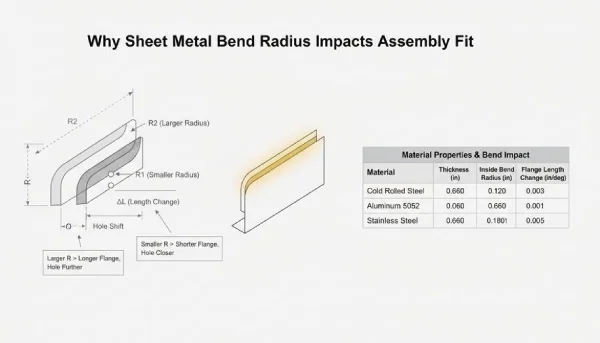
The sheet metal bend radius is an invisible yet critical factor in determining the success of an assembly. Even a slight deviation from the specified bend radius can alter the final geometry of the part, resulting in misaligned holes and changes in flange length. This is not merely a matter of tolerances; it is a functional issue.
Flange Length and Hole Proximity in Multi-Part Assemblies
When the sheet metal bend radius shifts, two things move with it: Flange Length and Hole Proximity. That’s where Multi-Part Assemblies start acting up.
Bend Radius Change:
Inside radius grows:Neutral axis shifts.Developed length increases.
Inside radius shrinks:Material compression rises.Effective flange shortens.
Impact on Component Fit:
Hole-to-edge distance:Reduced Clearance.Risk of bolt head Interference.
Slot alignment across parts:Stack-up errors.Weld gap variation.
Assembly-Level Risk:Exceeded Assembly Tolerance.Forced fit during fastening.Visible misalignment on final product.
A quick reference many teams use when checking sheet metal bend radius impact:
Material | Thickness (mm) | Inside Bend Radius (mm) | Flange Length Change (mm) |
Cold Rolled Steel | 2.0 | 2.0 | +0.15 |
Cold Rolled Steel | 2.0 | 3.0 | +0.32 |
Aluminum 5052 | 3.0 | 3.0 | +0.28 |
Stainless Steel | 1.5 | 1.5 | +0.10 |
Stress Concentration: Outside Bend Radius Effects on Fit
The outside side of a bend often gets ignored. Bad move. The Outside Bend Radius directly drives Stress Concentration, and that stress shows up as:Local Material Deformation.Extra Springback.Loss of Dimensional Accuracy.
Here’s how it plays out in real life:
Tight outside radius:Higher tensile strain.Reduced Fatigue Life.Micro-cracks near bend line.
Large outside radius:Lower stress.But longer developed length.Potential mismatch in mating brackets.
In cold rolled steel, springback can shift the final angle by 1–3°. That tiny angular drift affects Component Integrity, especially when multiple sheet metal bend radius features stack together in one frame. Bend radius control is not just about strength; it’s about fit that doesn’t fight back during installation.
Copper Sheet vs. Galvanized Steel: Considerations Regarding Material Grain Direction
The grain direction of copper and galvanized steel fundamentally determines the success of the bending process.
Material grain direction:
Parallel to the bend line: Higher risk of cracking; reduced bendability.
Perpendicular to the bend line: Increased ductility; wider safe forming window.
For copper, which exhibits high anisotropy, bending along the grain lines with a small bend radius will inevitably result in immediate fracture; therefore, we select an appropriate bend radius based on requirements and ensure the bending direction is perpendicular to the grain to fully utilize its ductility.
Galvanized steel presents different challenges: the sheet metal bend radius must be sufficiently large to prevent microcracks in the zinc coating, as these would compromise its corrosion resistance. If the grain-related behavior of these specific materials is ignored, the sheet metal bend radius calculated on paper will inevitably fail in actual operation.
Tolerance Requirements for Complex Part Geometry and Surface Finish
For parts with complex geometries, the sheet metal bend radius has evolved from a design feature into a primary driver of tolerance accumulation. Multiple bends on the same plane amplify any angular deviations, causing overall contour shifts and affecting flange parallelism. At the same time, surface finish requirements demand sufficiently large bend radii to prevent die marks and coating stretching on visible outer surfaces.
At Supro, we strictly control sheet metal bend radii during the forming process—not only to meet dimensional and geometric dimensioning and tolerancing (GD&T) requirements, but also to ensure that the design on the drawing maintains consistent geometry and flawless surfaces across every batch.
Looking for a reliable custom sheet metal fabrication companies?
Talk To Supro MFG Expert Team
Contact us for competitive ex-factory prices,
and a full range of technical support services.
Summary
From prototyping to mass production, mastering the sheet metal bend radius is the key distinction between design on paper and actual production—the former looks good on drawings, while the latter enables stable and cost-effective manufacturing. As we have detailed, this single variable determines material utilization, the accuracy of bend allowances, and ultimately impacts the assembly precision of complex components.
At Supro, our sheet metal bending services can meet all your needs. As a leading sheet metal bending manufacturer, we possess extensive expertise, technology, and state-of-the-art equipment, and understand the requirements and standards for sheet metal bending parts across various industries, including agriculture, medical, automotive, and aerospace. With 12 different types of sheet metal bending equipment, Supro offers one-stop sheet metal bending services for any industry, delivering high-quality products, professional customer service, and on-time delivery. If you have any questions or concerns regarding our sheet metal bending services, please contact us immediately—we are committed to meeting all your project requirements!