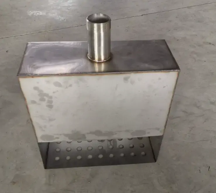



In the stamping process for metal gas tanks, wall thickness control is never merely a matter of dimensional accuracy—it directly affects the container’s pressure integrity and operational safety.
The deep-drawing process forms complex geometric contours by causing the sheet metal to flow radially into the die cavity during the forming of metal gas tank half-shells, but this process carries an inherent risk of localized thinning. When the material flow rate cannot keep pace with the punch’s impact speed, the corner regions are forced to compensate for geometric changes through stretching rather than flow, resulting in continuous thickness reduction.
Excessive thinning can develop into microcracks that are difficult to detect with the naked eye, or even through-wall fractures. Such defects are particularly dangerous in pressure vessels such as custom metal gas tanks—insufficient wall thickness directly reduces the pressure safety factor.
Traditional trial-and-error die development struggles to quantify safety margins, and the industry is gradually shifting toward predictive engineering methods centered on Forming Limit Diagrams (FLDs). Using finite element simulation platforms such as AutoForm and PAM-STAMP, metal gas tank manufacturers can predict thinning distributions, identify critical areas, and optimize process parameters before steel is cut, thereby ensuring that the thinnest point of the formed custom metal gas tank still meets design specifications and safety standards.
Understanding the Mechanism of Wall Thinning and Rupture in Metal Gas Tanks
During deep drawing, the thinning of the wall thickness in the half-shell of a metal gas tank results from the evolution of the stress state as the material flows into the die cavity. In the flange region, radial tensile stress and tangential compressive stress act simultaneously—the former drives material flow into the die cavity, while the latter arises from the material’s resistance to deformation.
When the radial tensile stress exceeds the material’s plastic flow capacity, wall thickness begins to decrease. This thinning is most concentrated in the corner regions of the metal gas tank, where a sudden change in curvature forces the material to compensate for geometric changes through stretching rather than flow.
Thinning is not uniformly distributed. In the deep drawing of a metal gas tank, the greatest thinning occurs at the punch radius, and the degree of thinning increases as the die radius decreases. When localized thinning accumulates to a critical value, the material enters the necking stage—a precursor to failure as defined by the Forming Limit Diagram (FLD). Once the strain path crosses the Forming Limit Curve (FLC), microcracks initiate and rapidly propagate into through-wall fractures.
For pressure vessels such as custom metal gas tanks, the cascade of events from wall thinning to fracture is particularly dangerous—insufficient wall thickness directly reduces the pressure safety factor, and microcracks often cannot be detected through conventional visual inspection. Understanding this mechanical mechanism is a prerequisite for subsequently optimizing die design and controlling wall thinning through simulation.
Root Causes of Wall Thinning and Fracture in Metal Gas Tank Stamping
There are three primary root causes of wall thinning and fracture during the stamping of metal gas tanks: die geometry (holding force, draw bead layout, fillet radius), process conditions (lubrication, punch speed, draw ratio), and material properties (elongation, anisotropy, edge quality). Each factor alters the strain path and may cause localized wall thinning to exceed the forming limit.
Die Design Parameters
During the forming process of custom metal gas tanks, die geometry directly determines the strain path. The blank holding force (BHF) must be precisely calibrated—insufficient BHF leads to wrinkling, while excessive BHF causes tearing near the corners of the punch.
The punch radius is particularly critical: wall thickness reaches its minimum when the part’s wall loses contact with the punch; the smaller the radius, the more concentrated the tensile stress becomes, thereby accelerating localized thinning.
The geometry of the draw bead further adds to the complexity—increasing the height of the convex edge suppresses wrinkling but exacerbates thinning, while increasing the radius of the reverse edge produces the opposite effect.
For pressurized metal gas tank applications, even minor deviations in die radius can compromise wall thickness integrity in critical corner areas.
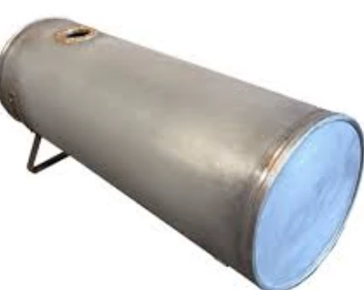
Process Conditions for Deep-Drawn Metal Gas Tanks
Process parameters determine the friction and flow dynamics during the deep-drawing of metal gas tanks. Lubrication effectiveness can be quantified by the coefficient of friction—for deep-drawn stainless steel, the minimum thinning rate is 5.42% when the coefficient of friction is 0.024; however, when the coefficient of friction exceeds 0.17, the tendency for cracking increases significantly.
The effect of punch speed is equally significant: increased speed exacerbates strain localization, and the maximum thinning always occurs at the leading edge radius of the punch. Reducing punch speed improves the uniformity of the thickness distribution.
For the manufacturing of metal gas tanks, optimizing the interaction between lubrication and speed is crucial for maintaining uniform wall thickness across the formed geometry.
Materials for Metal Gas Tanks
The mechanical properties of the blank fundamentally determine the formability of custom metal gas tanks. Elongation at break is the primary indicator of ductility, while plastic anisotropy—quantified by the Rankford r-value—significantly influences thinning behavior relative to the rolling direction.
Materials with high in-plane anisotropy are more prone to ear-like defects during deep drawing, thereby increasing the difficulty of wall thickness control. The Forming Limit Diagram (FLD) comprehensively considers these variables and defines the boundary between safe deformation and failure.
For pressurized metal gas tank applications, the selection of deep-drawing grade steel with high uniform elongation and controlled anisotropy is non-negotiable—material certification must verify compliance with the FLD requirements prior to product release.
Only 4 steps
online custom metal fabrication parts
Contact our experts team and experience the efficiency and economic benefits of digital metal fabrication services.
Upload Design Files
STL , STEP (.stp), IGES (.igs), (.ZIP), or PDF.
Also be a sample or an idea
Quote & Design Analysis
Instant factory quotes and DfM reports, the most reasonable solution.
Manufacturing Begins
Digital processes can initiate order tasks within 24 hours.
On-Time Delivery
Keeping delivery promises, approved by 3000+ Global Company buyers.
Die Design for Deep Drawing of Metal Gas Tanks
Traditional die design for deep drawing of metal gas tanks primarily relies on trial-and-error methods, which cannot quantitatively assess the safety margin against fracture caused by wall-thickness reduction. Supro has shifted to predictive engineering design based on Forming Limit Diagrams and finite element analysis, enabling systematic risk assessment, parameter optimization, and validation prior to die manufacturing, thereby avoiding costly iterative rework.
Limitations of the Trial-and-Error Approach
The trial-and-error approach remains the traditional method for developing metal gas tank dies, but its limitations are significant. Die trial costs alone account for approximately 30% of the total cost of deep-drawing dies, and each iteration—from die modification to retesting on the press—typically takes several months.
For multi-stage deep-drawing processes involving complex geometries, such as custom metal gas tank half-shells, numerous parameters must be evaluated: intermediate die geometry, blank shape, sheet thickness, holding force, and lubrication conditions. The trial-and-error method cannot systematically optimize this multivariate environment.
Furthermore, critical defects such as local thinning often cannot be detected through visual inspection during trial runs. This means that a die may pass initial trials but produce non-compliant wall thicknesses during mass production—a risk that is unacceptable for pressurized metal gas tank applications, as wall thickness integrity directly determines the safety margin.
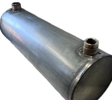
The Need for Predictive Engineering
Predictive engineering addresses the fundamental shortcomings of the trial-and-error approach in custom metal gas tank die design. Formability Limit Diagrams (FLDs) provide a quantitative framework for assessing formability—they define the boundary between safe deformation and local necking or fracture.
Finite element platforms such as AutoForm and PAM-STAMP support virtual prototyping, thereby replacing physical prototyping iterations. Their predictive capabilities are well-documented: simulation results for deep-drawn parts show that the deviation in thickness prediction is as low as 5.45% compared to experimental results.
Industry case studies further validate the effectiveness of this approach—a certain automotive supplier used PAM-STAMP simulations to reduce the die design cycle from 6–12 months to 1 month, with die performance fully consistent with the predicted results.
For a metal gas tank manufacturer, adopting a simulation-driven development model means identifying critical thinning areas, optimizing draw bead geometry, and verifying wall thickness based on safety factors before steel is cut—thereby avoiding costly rework and ensuring dimensional accuracy from the first production run.
Are you looking for reliable & cost-effective
China metal fabrication manufacturer
More than 150,000 OEM metal fabrication products delivered to 5,000+ global buyers.
And benefit from it!
Simulation-Driven Development of Stamping Dies for Metal Gas Tanks Using AutoForm and PAM-STAMP
Simulation-driven die development for metal gas tank forming processes relies on two industry-standard platforms: AutoForm and PAM-STAMP. AutoForm enables fast and accurate simulation of processes such as deep drawing, re-stamping, trimming, flanging, and hemming, and offers powerful springback prediction capabilities.
PAM-STAMP supports multi-stage processing operations, handles advanced materials including ultra-high-strength steel (UHSS) and aluminum, and predicts critical formability issues in complex geometries, such as thinning, wrinkling, and fracture. Its simulation accuracy has been thoroughly validated: a validation study on deep-drawn parts showed that the deviation between predicted thickness values and experimental results was only 5.45%.
For custom metal gas tanks, key simulation outputs include: thickness distribution maps to identify localized thinning areas, forming limit diagrams (FLDs) to assess fracture risk, and springback predictions that influence subsequent welding alignment.
Iterative optimization capabilities are equally crucial—engineers can systematically evaluate various parameters: blank clamping force, draw bead geometry, lubrication coefficient, and punch speed.
This virtual prototyping approach replaces costly physical prototyping iterations. As a result, dimensional accuracy is ensured from the first production run, avoiding costly rework and significantly shortening the die development cycle.
Practical Engineering Measures for Controlling Thin Walls in Metal Gas Tanks
For deep-drawn metal gas tanks, there are three practical measures to address the issue of thinning walls: optimizing the geometry of the draw beads, allowing wall thickness tolerances in high-stress areas, and selecting materials with sufficient elongation and controllable anisotropy. The combined application of these control measures reduces the risk of fracture and ensures the integrity of custom metal gas tanks.
Draw Bead Optimization
During the deep drawing process of custom metal gas tanks, the geometry of the draw bead has a primary influence on wall thickness distribution.
The draw bead controls the flow of material into the die cavity by forcing the sheet metal to repeatedly bend and stretch, thereby generating a constraining force that suppresses the formation of wrinkles. However, this constraint comes at a cost: systematic optimization studies indicate that draw bead height and radius are the primary parameters affecting wall thinning, contributing 41.78% and 43.6%, respectively.
While increasing the height of the draw bead effectively suppresses wrinkling, it inevitably exacerbates local thinning; conversely, increasing the radius of the reverse draw bead produces the opposite effect.
For custom metal gas tanks, simulation-based draw bead optimization—that is, the iterative evaluation of bead height, radius, and position—enables engineers to strike a balance between preventing wrinkling and controlling thinning.
A fully optimized draw bead configuration can significantly improve formability by simultaneously minimizing both wrinkling and thinning.
Thickness Tolerance Allowance
For pressurized metal gas tank applications, specifying wall thickness tolerances in critical areas is not an option—it is a safety requirement. The deep drawing process inherently results in wall thickness non-uniformity, with the most severe thinning concentrated at the punch corner radius, where the workpiece wall loses contact with the punch.
While traditional practices focus on achieving nominal thickness, pressure vessel design requires a different approach: sufficient wall thickness must be retained in high-stress areas to ensure that the minimum wall thickness after forming still meets the safety factor requirements for pressure vessels.
This requires predefining acceptable thinning limits, after which the die geometry must be designed to ensure that the predicted thinning at critical corners remains within these limits.
In the manufacturing of metal gas tanks, this means that thickness tolerance allowances are input parameters for die design, not output results—process design must ensure that sufficient material is retained at the points of highest pressure stress.
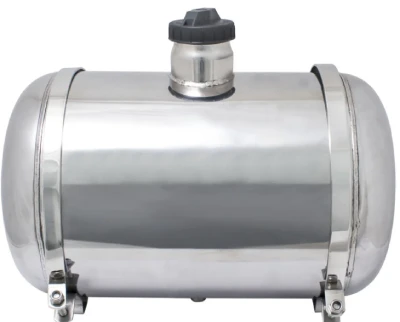
Material Selection and Preparation for Custom Metal Gas Tanks
The choice of material fundamentally determines whether a metal gas tank can be deep-drawn without excessive thinning or fracture. Among the material properties, two are critical: ductility (elongation at break) and normal anisotropy (Rankford’s r-value).
Higher ductility means greater capacity for plastic deformation before necking occurs, while higher normal anisotropy provides resistance to wall-thickness reduction during the drawing process.
Deep-drawing grade steels (such as gapless steel (IF)), due to their superior R-value and uniform elongation, consistently outperform traditional drawing-grade steels in terms of resistance to wall thinning.
For custom metal gas tank applications, HP295 steel is typically specified; its microstructure, texture, yield ratio, and plastic strain ratio (R-value) are key selection criteria.
In addition to mechanical properties, blank preparation is equally critical—burrs and edge interlaminar delamination act as stress concentration points and can cause cracks during forming. In the manufacturing of metal gas tanks, material certification must verify compliance with FLD standards, and blanks must be prepared in accordance with edge quality standards to eliminate stress concentration points before the first drawing stroke.
Looking for a reliable custom sheet metal fabrication companies?
Talk To Supro MFG Expert Team
Contact us for competitive ex-factory prices,
and a full range of technical support services.
Typical Case Study—Thin-Wall Treatment of Corner Radii in Metal Gas Tank Half-Shells
In the manufacturing of metal gas tanks, the corner radii of each half-shell are the most critical areas for wall thinning.
For typical metal gas tank half-shells with corner radii of 8–12 mm, the material in this area undergoes severe bending and straightening as it is drawn into the die cavity. The strain path in this area often approaches or exceeds the forming limit curve (FLC), making it the primary location for initial necking and potential fracture.
Take, for example, the production of a steel metal gas tank half-shell with a specified corner radius of 10 mm. Initial die trials using conventional parameters showed that wall thickness reduction in the corner area exceeded 25%—far higher than the 20% upper limit typically specified for pressure vessel applications.
Furthermore, the thinning was unevenly distributed: wall thinning was most severe near the punch tip, while the area near the flange remained relatively thick. This localized thinning directly compromised the safety margin of the pressure vessel, as the minimum wall thickness after forming fell below design requirements.
To address this issue, simulation-based interventions were required. Using AutoForm software, the forming process was modeled in conjunction with the yield criterion proposed by Barlat and Lian in 1989. Simulation results indicate that increasing the punch nose radius and the die corner radius can reduce the thinning ratio, but at the cost of increased punching force.
More importantly, the draw bead geometry was optimized—increasing the height of the convex edge suppresses wrinkling but exacerbates thinning, while increasing the radius of the reverse edge produces the opposite effect. Through an optimized configuration, a balance was achieved between these conflicting parameters, reducing the corner thinning rate from 25% to approximately 18%, bringing it within an acceptable range.
The redesigned die was experimentally validated, and thickness measurements confirmed that the deviation from the simulation predictions was within 5.45%. Final result: the custom metal gas tank half-shell exhibits uniform wall thickness at critical corner radii and has met both dimensional specifications and pressure containment safety requirements since the start of production.
Conclusion
The long-standing challenges of wall thinning and fracture during the deep drawing of metal gas tanks cannot be resolved through trial-and-error die development. As mentioned earlier, the mechanical mechanisms behind localized thinning are well understood, and their root causes—die geometry, process conditions, and material variables—can be controlled through predictive engineering.
By utilizing simulation platforms such as AutoForm and PAM-STAMP, combined with practical measures—including draw bead optimization, wall thickness tolerance allowance, and rigorous material selection—these approaches ensure that the minimum formed wall thickness of every custom metal gas tank meets pressure containment requirements.
Supro is a specialized custom metal gas tank manufacturer. Leveraging advanced equipment, extensive manufacturing experience, and a professional engineering team, we provide flawless custom metal gas tank services to over 3,000 companies worldwide and offer genuine manufacturer quotes.
For inquiries regarding technical specifications, customized project solutions, or OEM partnerships, please contact Supro immediately. Our professional engineering team is always ready to tailor exclusive application solutions for you.