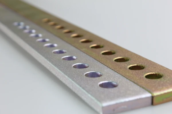

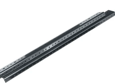
When selecting hardware for heavy-duty electrical cabinets and industrial automation equipment, engineers typically rely on mounting rails as critical load-bearing components. However, one of the most difficult-to-detect defects in custom sheet metal fabrication is microcracks that form at bends. These hairline cracks occur when the localized tensile stress on the fibers on the outer side of the bend radius exceeds the ultimate tensile strength of a specific alloy.
If this defect goes undetected during quality inspection, dynamic loads and continuous mechanical vibrations will cause these microscopic defects to propagate, leading to premature structural failure of custom mounting rails in the field. This is rarely due to abnormalities in the raw material; rather, the root cause lies in a mechanical mismatch between the internal bending radius (R value) and the material thickness, or a failure to keep the bending axis perpendicular to the steel’s natural rolled grain orientation.
This article analyzes the mechanical principles of metal forming and details the precise bending die strategies required to manufacture structurally sound, defect-free precision mounting rails that meet the demands of rigorous industrial applications.
Flexural Mechanics: Why Do Microcracks Form in Mounting Rails?
To understand the root causes of defect formation in metal mounting rails, it is essential to first examine the specific metallurgical behavior that occurs during the forming process on a press brake.
When a flat metal sheet undergoes plastic deformation in a V-die, the material’s cross-section is subjected to intense and opposing mechanical stresses, with the neutral axis serving as the dividing line. The internal fibers are subjected to compressive stress, while the outer surface experiences significant tensile deformation and is subjected to extreme localized tensile stress.
If the applied tensile force exceeds the elongation limit and ultimate yield strength of the specified alloy—which is typically caused by using a punch radius that is too large—the outer fibers will undergo physical tearing, resulting in hairline microcracks along the bend line.
For any structural precision mounting rail, this molecular-level degradation immediately compromises the component’s load-bearing capacity and long-term fatigue resistance.
If the material’s elongation limit is disregarded during the bending process, a mounting rail that appears visually acceptable on the surface may harbor these hidden cracks. Predicting and managing material flow during the initial die setup phase is essential to ensure that every custom mounting rail can withstand continuous dynamic loads in an industrial environment.
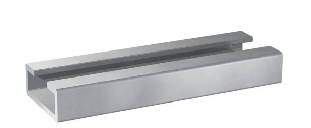
Root Cause Analysis of Microcrack Defects in Mounting Rails
When structural failure occurs in precision mounting rails, it is rarely caused by random material anomalies. In precision sheet metal fabrication, these microcracks typically stem from two key engineering calculation errors: mismatched press brake die geometry and neglect of the material’s inherent metallurgical properties.
Mismatch Between the Bending Radius (R Value) of the Mounting Rail and Material Thickness
The most common manufacturing error in the production of mounting rails is that the inner bending radius (R value) of the press brake punch used is too sharp for the specified material thickness. During plastic deformation, the outer boundary of the metal undergoes significant stretching. If the selected die radius forces the material beyond its maximum elongation threshold, the outer fibers will immediately fracture.
For heavy-duty carbon steel or stainless steel—commonly used in metal mounting rails—engineers typically specify that the minimum bending radius should be 1 to 1.5 times the material thickness (1T–1.5T). When manufacturers disregard this die ratio solely to achieve more compact and aesthetically pleasing corners, the structural integrity of custom mounting rails is severely compromised. Specifying the correct punch radius keeps localized tensile stresses below the alloy’s fracture point, thereby effectively preventing the formation of microcracks.
Key Influence of Rolled Grain Orientation
The second major cause of bending fractures involves the metallurgical anisotropy of the raw metal sheet. During the cold-rolling process at the steel mill, the internal metal grain structure becomes elongated along the rolling direction. If, when laying out the floor plan for precision mounting rails, the supplier aligns the longitudinal bending line parallel to this natural grain direction, the bending machine will effectively tear the grain fibers, which almost inevitably leads to microcracks.
To ensure maximum durability, the layout must be strategically planned within the laser cutting software. The bending axis must be transverse to the rolled grain direction—ideally, perpendicular to it. Although this transverse bending technique typically results in a slight reduction in material utilization, it is absolutely non-negotiable for producing defect-free custom mounting rails capable of withstanding harsh industrial vibrations.
Only 4 steps
online custom metal fabrication parts
Contact our experts team and experience the efficiency and economic benefits of digital metal fabrication services.
Upload Design Files
STL , STEP (.stp), IGES (.igs), (.ZIP), or PDF.
Also be a sample or an idea
Quote & Design Analysis
Instant factory quotes and DfM reports, the most reasonable solution.
Manufacturing Begins
Digital processes can initiate order tasks within 24 hours.
On-Time Delivery
Keeping delivery promises, approved by 3000+ Global Company buyers.
Engineering Solutions for Defect-Free Mounting Rail Manufacturing
To completely eliminate the problem of bending fractures, it is essential to shift from passive inspection to proactive “Design for Manufacturability” (DFM). By rigorously optimizing die geometry, grain orientation in the flat pattern, and the tempering condition of the material, we ensure that every precision mounting rail provides absolute structural integrity for demanding industrial applications.
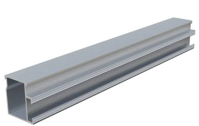
Optimizing Press Brake Dies and R Values
To eliminate tensile fractures during processing, engineers must calculate and implement the optimal press brake die geometry for each specific metal mounting rail.
We do not force bends at acute angles that cannot be achieved; instead, we stipulate that the inner bend radius (R value) must safely exceed the material’s minimum threshold. For heavy-duty mounting rails, it is standard practice to use a punch radius equal to or slightly greater than the sheet thickness (1T to 1.5T). Additionally, the V-shaped die opening must be carefully calibrated—typically 8 times the material thickness for low-carbon steel—to ensure a smooth and controlled bending process.
By optimizing this specific die combination, we have significantly reduced tensile stress on the outer surface. This rigorous DFM approach ensures that the final custom mounting rails maintain absolute structural integrity, with absolutely no microscopic cracks—invisible to the naked eye—along critical bending axes.
Lateral Bending: Layout of Mounting Rail Flat Patterns
The anisotropy of the material directly affects bending strength. To address this issue, Supro MFG implements strict laser nesting procedures to control the layout of the flat pattern for each metal mounting rail.
Before any CNC cutting begins, our CAM engineers program the nesting software so that the longitudinal bending lines are oriented perpendicular to the material’s natural rolled grain direction. Bending perpendicular to the grain direction (ideally at a 90-degree angle) forces the molecular fibers to fold rather than fracture. Although this strategic layout occasionally results in a slight reduction in nesting efficiency, it is absolutely essential for ensuring quality.
For heavy-duty mounting rails, this perpendicular-to-grain bending technique completely prevents longitudinal fractures, thereby maximizing the long-term load-bearing reliability of the finished product.
Material Selection and Tempering Considerations for Mounting Rails
In addition to die design and layout, preventing microcracks requires specifying the correct metal condition prior to forming. Extremely hard materials or high-temperature alloys have low ductility and are therefore highly prone to fracture during small-radius bending.
When customers request high-strength custom mounting rails, we carefully evaluate the heat-treated condition of the alloy. For example, attempting to bend rigid T6-condition aluminum often results in immediate cracking. In such cases, we recommend selecting an alloy grade with better formability (such as 5052-H32) or performing localized annealing prior to bending. This controlled heat treatment softens the specific bending areas, restoring their ductility without sacrificing the overall rigidity of the metal mounting rails.
Proper material selection ensures that the manufactured precision mounting rails can withstand the demanding forming process while meeting precise mechanical specifications.
Quality Control Procedures for Mounting Rail Production
The implementation of reliable engineering solutions must be validated through rigorous quality assurance processes. Relying solely on visual inspection is completely insufficient, as initial cracks along the bending axis of metal mounting rails are typically microscopic. To ensure zero structural defects, professional sheet metal fabricators must employ non-destructive testing (NDT) methods.
During the critical First Article Inspection (FAI) process, quality assurance technicians perform liquid penetrant inspection (LPI) on the bent corners. This technique uses capillary action to introduce a visible dye into surface cracks, thereby immediately revealing any stress cracks that could compromise the mounting rail. In addition to standard dimensional verification, high-magnification surface analysis (using a 10x to 20x optical magnifier).
Once the initial setup is approved, rigorous Statistical Process Control (SPC) and routine AQL sampling are performed throughout the entire production process. This continuous monitoring ensures that progressive wear on the bending dies does not inadvertently alter the R-value and lead to delayed cracking.
By implementing these advanced metallurgical quality control standards, custom mounting rails deliver absolute reliability, effectively eliminating the risk of catastrophic failure during field deployment.
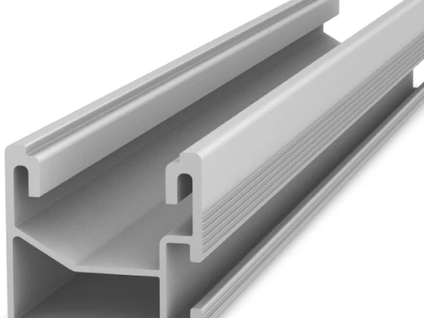
Partnering with Supro MFG to Produce Precision Mounting Rails
To procure reliable structural mounting rails, it is essential to understand that surface aesthetics are meaningless without internal metallurgical integrity. At Supro MFG, we bridge the gap between engineering theory and shop-floor execution. Our in-house engineering team conducts mandatory Design for Manufacturability (DFM) reviews before any steel is processed.
We proactively analyze yield strength, precisely calculate bending allowances, and strictly enforce cross-grain laser nesting protocols to ensure your custom mounting rails are completely free of microcracks during the forming process.
By combining high-precision CNC press brakes with our rigorous First Article Inspection (FAI) and Non-Destructive Testing (NDT) protocols, we proactively eliminate mechanical risks associated with mounting rail manufacturing. Trust Supro MFG to be your dedicated sheet metal fabrication partner in China. Whether you are specifying high-tolerance mounting rails for automated equipment or sourcing complex industrial enclosures, we guarantee absolute dimensional accuracy and structural reliability.
Conclusion
Avoiding microcracks during mounting rail manufacturing is not a matter of luck but requires strict adherence to the principles of metallurgical science. A forward-thinking Design for Manufacturability (DFM) approach is required—specifically, optimizing internal bend radii to align with the material’s yield strength and orienting the flat layout perpendicular to the rolled grain structure. By applying these mechanical principles in conjunction with rigorous non-destructive testing, we ensure absolute reliability under dynamic loads.
Partner with Supro to ensure that every custom mounting rail is ready for on-site installation upon delivery, thereby completely eliminating the high risks associated with premature structural failure in critical industrial applications.
For inquiries regarding technical specifications, customized project solutions, or OEM partnerships, please contact Supro immediately. Our professional engineering team is always ready to provide you with a tailored application solution.