

The grounding stud in a junction box is not merely a convenience feature; it is the primary interface for the equipment’s grounding conductor, and its integrity directly determines whether the enclosure can provide a low-impedance fault current return path to the power source.
According to the UL 508A standard, industrial control cabinet enclosures must be equipped with conductive grounding terminals to ensure a secure connection to all connected metal components. Thread stripping or coating contamination on these terminals can cause electrical junction boxes to fail to meet specifications during field installation, often leading to costly rework, project delays, and potential violations of Section 250.8 of the National Electrical Code (NEC).
This article examines the failure mechanisms of grounding stud threads in custom junction boxes from a manufacturing engineering perspective and outlines the process control measures required to ensure that the threads can withstand powder coating, transportation, and operation with electric torque wrenches.
The Critical Role of Grounding Studs in Junction Box Safety
Grounding studs in electrical junction boxes provide a critical grounding connection point for equipment grounding conductors. The integrity of their threads directly affects the impedance of the fault current path and compliance with UL 508A and Section 250.8 of the National Electrical Code (NEC); therefore, this is a non-negotiable quality attribute in sheet metal fabrication.
Regulatory and Performance Requirements
The grounding stud in a custom junction box serves as the primary connection point for the equipment grounding conductor. The UL 508A standard stipulates that all non-conductive metal parts must be connected via a conductive connection to form a low-impedance fault current path.
NEC Section 250.8 requires that grounding terminals be connected using certified methods—including certified pressure connectors, terminal blocks, and machine-screw-type fasteners with at least two turns of engagement.
For junction box manufacturers, this means that the thread geometry, material integrity, and surface condition of the studs are prerequisites for compliance with the code. Any deviation will affect the enclosure’s ability to obtain UL marking and result in its failure to meet code requirements during installation.
Why Thread Integrity Is Critical for Junction Boxes
Thread integrity directly determines whether the grounding studs of an electrical junction box can withstand the torque specified for field installation. National Electrical Code (NEC) 250.8(A)(5) stipulates that machine screw terminals must have at least two threads engaged. Thread damage—whether caused by fastener material that is too soft, excessive torque, or contamination from powder coatings—can reduce the number of engaged threads below this threshold, thereby increasing the resistance of the grounding path.
UL 486A provides torque reference values, and electricians must ensure these values are met without causing thread damage. Once a problem arises with the terminal, a routine installation can turn into a costly rework. This single interface determines the reliability of the entire grounding system.
Common Failure Modes of Threads on Electrical Junction Box Grounding Studs
Thread failure in electrical junction box grounding studs primarily stems from three distinct factors: material selection, manufacturing processes, and field installation. Each failure mode has its specific root cause—and corresponding preventive measures.
Material-Related Failures
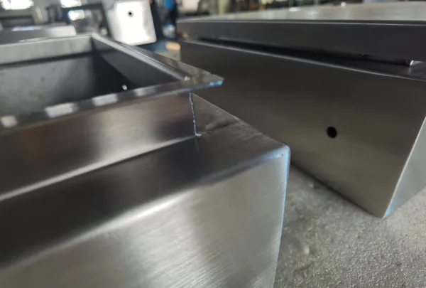
Thread failure in grounding studs for custom junction boxes can typically be traced back to the base material. If the specified hardware lacks sufficient hardness—such as low-grade steel or unhardened brass—plastic deformation occurs when subjected to installation torque. The thread flanks yield rather than spring back, thereby reducing the effective shear area and preventing the clamping force required to establish a low-resistance ground connection.
Although copper has excellent electrical conductivity, it is too ductile for threaded stud applications and is prone to stripping under load. For junction box manufacturers, material selection must strike a balance between electrical conductivity and mechanical strength—which is why copper alloys or plated steel are typically specified instead of pure copper.
The thread geometry of the junction box is also critical: rolled threads cause work hardening of the material during the forming process, resulting in far greater resistance to stripping than cut threads. When an electrical junction box is shipped with soft fasteners, this failure has effectively been built into the product from the design stage—it only becomes apparent when an electrician uses a torque wrench.
Process-Related Failures
The threads on many junction box grounding studs are damaged on the powder coating line. If the threaded areas are not masked before powder coating, the coating fills the thread grooves and alters the pitch diameter. As a result, the threads no longer meet the specified fit grade—the effective engagement area is reduced, and the coating itself forms an insulating layer between the stud and the grounding terminal. This dual mechanical and electrical failure causes custom junction boxes to fail to meet code requirements at the time of installation.
Incorrect installation of self-riveting studs can also lead to defects. Excessive installation pressure can cause deformation of the base plate metal around the stud, while insufficient pressure fails to seat the rivet ring properly. Both situations weaken the stud’s pull-out resistance and compromise its ability to maintain thread integrity under torque.
Process-related failures are entirely preventable—provided that shielding procedures are strictly followed and calibrated installation equipment is used.
Installation-Related Failures
On-site installation of junction boxes can lead to the final type of thread failure. When electricians apply torque without using calibrated tools, they often exceed the stud’s rated load capacity, resulting in thread stripping at the wiring terminals.
Misalignment—that is, screwing the nut in at the wrong angle—can damage the main threads and create stress concentrations, which are further exacerbated under load. The National Electrical Code (NEC) requires that at least two full threads be fully engaged in machine screw terminal connections; if this requirement cannot be met due to a stud that is too short or excessive terminal stacking, the connection will lack the mechanical strength necessary to withstand a fault current.
Furthermore, vibration and thermal cycling can further exacerbate the already precarious thread damage, causing the connection to gradually loosen and ultimately resulting in a loss of ground continuity.
Only 4 steps
online custom metal fabrication parts
Contact our experts team and experience the efficiency and economic benefits of digital metal fabrication services.
Upload Design Files
STL , STEP (.stp), IGES (.igs), (.ZIP), or PDF.
Also be a sample or an idea
Quote & Design Analysis
Instant factory quotes and DfM reports, the most reasonable solution.
Manufacturing Begins
Digital processes can initiate order tasks within 24 hours.
On-Time Delivery
Keeping delivery promises, approved by 3000+ Global Company buyers.
Material Selection and Hardware Specifications for Junction Box Studs
The reliability of grounding studs in electrical junction boxes begins at the material specification stage. Selecting the correct stud material and thread geometry will determine whether the stud can withstand the specified torque without plastic deformation and maintain long-term electrical continuity under operating conditions.
Selecting the Appropriate Stud Material
The ideal material for grounding studs should strike a balance between electrical conductivity and mechanical strength. Although copper offers excellent electrical conductivity, it lacks the hardness required for threaded applications—pure copper is prone to peeling under torque.
The industry standard for junction box applications is copper-clad low-carbon steel, which provides the conductive surface required for low-resistance grounding while maintaining the core hardness necessary to ensure thread integrity.
Surface-hardened carbon steel studs with a surface hardness of at least Rockwell C45 and a core hardness of Rockwell C29–38 provide the shear strength needed to withstand on-site torque while preventing thread yield.
In corrosive environments, 300-series stainless steel can serve as an alternative, although its conductivity is approximately 1/40th that of copper—this trade-off must be evaluated based on the operating conditions of the custom junction box.
Considerations for Junction Box Thread Design
In custom junction boxes, thread geometry directly affects the stud’s resistance to slippage and its ability to meet the minimum thread engagement requirements specified in National Electrical Code (NEC) Section 250.8(A).
In grounding stud applications, rolled threads are inherently superior to cut threads. The cold-forming process induces work hardening in the material, increasing tensile strength by approximately 10% and significantly enhancing shear and fatigue resistance. While cut threads sever material fibers and create stress concentration points, rolled threads displace material along continuous, unbroken grain lines that follow the thread profile—significantly enhancing their resistance to slippage.
The rolling process also produces smooth, polished thread roots and flanks, free of cutting marks that could act as stress concentration points. The selection of thread form for junction boxes is also critical: compared to fine-pitch threads of the same nominal size, coarse-pitch threads provide a larger engagement area and greater resistance to slippage.
In electrical junction box applications, Unified threads such as 10-32 UNF are standard specifications, but the thread fit grade must be explicitly specified—typically 2A according to the ASME B1.1 standard—to ensure consistent engagement and torque performance.
Process Control During Stud Installation in Junction Boxes
Selecting the appropriate stud material and thread geometry is essential for ensuring the grounding integrity of junction boxes, but these factors alone are not sufficient. The installation process itself determines whether the studs can achieve their designed performance. Precision equipment and standardized operating procedures are the two pillars of reliable stud installation.
Precision Installation Equipment
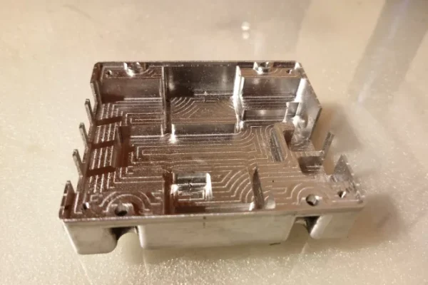
Equipment used to install grounding studs in electrical junction boxes must apply a controlled and repeatable force to achieve proper riveting while avoiding damage to the threads or the base metal plate.
Haeger hydraulic presses are widely recognized as the industry standard for the installation of self-clinching fasteners, with an adjustable force range of 400 to 12,000 pounds (1.8 to 53.4 kilonewtons). These machines utilize advanced servo-driven systems that display force and displacement curves in real time on a 15-inch touchscreen computer, enabling operators to verify each installation against established parameters.
The PMCS control system collects production data—including cycle times, process curves, and alarm history—for remote monitoring and analysis. When installing studs with force monitoring, the system immediately detects instances of incomplete seating or over-compression.
Consistency in Junction Box Installation
Ensuring consistency in stud installation requires standardized procedures, calibrated equipment, and strict process control. Self-riveting fasteners are installed by pressing them into appropriately sized holes using a press; the compression action embeds the fastener and locks it securely into the sheet metal, providing high resistance to torsional and thrust forces.
The press must apply force perpendicular to the sheet metal surface, and the stud shank must be perpendicular to the hole opening before force is applied. For junction box manufacturers, this means establishing standardized setup procedures—including specific force values for each stud type and sheet metal thickness—and verifying them through first-article inspection.
Supro regularly calibrates the press force monitoring system and conducts process sampling at specified intervals to ensure that the grounding studs installed in every custom junction box that rolls off the production line meet the same mechanical specifications.
Looking for a reliable custom sheet metal fabrication companies?
Talk To Supro MFG Expert Team
Contact us for competitive ex-factory prices,
and a full range of technical support services.
Protecting the Threads of Junction Boxes During the Powder Coating Process
The powder coating process—while essential for corrosion protection—poses a significant risk to the threads of electrical junction box grounding studs if not properly controlled. Unmasked threads can become filled with coating material, altering the pitch diameter and forming an insulating layer, which impairs both mechanical engagement and electrical conductivity.
The Necessity of Masking
Masking threaded grounding studs prior to powder coating is not an optional step—it is a functional requirement. Powder coatings are non-conductive; any coating deposited on the thread surface will form an insulating layer between the stud and the grounding terminal, thereby directly disrupting the electrical continuity of the electrical junction box’s grounding path.
In addition to causing electrical failures, the buildup of coating alters the pitch circle diameter—which increases by a factor of four the thickness of the coating. Given that typical industrial powder coating thicknesses range from 2 to 6 mil, even a thin coating can result in an effective thread engagement depth that falls below the minimum requirements specified by the National Electrical Code (NEC).
During the junction box manufacturing process, unmasked threads transform a routine surface treatment process into a potential source of on-site failure—manifesting as an electrician’s inability to achieve the specified torque value or to establish a code-compliant ground connection.
Selecting the Appropriate Masking Material
The masking material for grounding studs in electrical junction boxes must be able to withstand the entire powder coating curing cycle without degrading or losing its seal.
Powder coating curing ovens typically operate at 180–200°C (356–400°F), whereas standard masking tape fails at temperatures exceeding 120°C. Silicone is the industry standard for this application—it maintains dimensional stability at curing temperatures and can be reused for 100 or more production cycles.
For studs, high-temperature silicone caps can fully cover the threaded portion. For irregular junction areas, silicone stepped plugs with integrated flanges can simultaneously protect both the threads and the surrounding contact pads.
Selecting the correct masking geometry ensures a tight seal that prevents powder infiltration while allowing for easy removal after curing—thereby eliminating the need for thread trimming after the custom junction box has been painted and avoiding the risk of damaging the studs.
Best Practices for Junction Box Masking
Effective masking requires a rigorous application process. Masking covers must be installed before the junction box enters the paint line. Any powder that penetrates the seal will require thread trimming or tapping after curing; both of these operations are time-consuming and may damage the thread geometry.
Masking components must be installed securely enough to withstand the blast of electrostatic powder particles, but not so tightly as to cause stud deformation or make removal difficult. After the curing cycle is complete, the masking components should be removed and inspected for damage; they may only be reused after being confirmed undamaged.
A systematic masking procedure—including visual inspections before coating and after removal—ensures that the threads of every electrical junction box grounding stud remain clean and fully functional after powder coating, capable of withstanding the specified torque and establishing a low-resistance ground connection.
Inspection and Quality Assurance of Junction Boxes
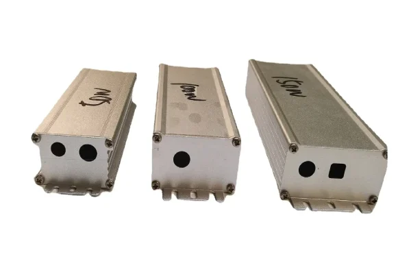
For custom junction boxes, inspection serves as the final quality control step—it verifies that the material selection, installation, and coating protection ensure the threads can withstand the specified torque and establish a low-resistance grounding path.
In-Process Inspection
In-process inspection of the junction box grounding studs begins immediately after installation and continues until the end of the powder coating line.
First-article inspection is used to verify the stud installation position, perpendicularity to the sheet metal surface, and the integrity of the rivet rings—ensuring that fasteners are fully seated and the base material is not deformed. Prior to coating, a visual inspection confirms that each stud has been properly masked and that the masking material has not shifted during handling. After the powder coating curing cycle is complete, the masking layer is removed, and the exposed threads are inspected for cleanliness.
The most critical process inspection is the pass/fail thread gauge test: the pass gauge must insert freely and without resistance to full depth; the insertion depth of the fail gauge must not exceed three turns. This verifies that the pitch circle diameter of the threads has not changed due to coating penetration—a direct test of the stud’s ability to withstand on-site torque. Only electrical junction boxes that pass the “pass/fail” inspection at this stage may proceed to final assembly and electrical testing.
Final Verification of the Junction Box
Final verification confirms that the entire custom junction box grounding system complies with code and standard requirements.
Grounding continuity test—in accordance with UL 508A—measures the resistance between the grounding stud and all connected metal components. The measured value must not exceed 0.1 Ω; readings above this threshold indicate an inadequate connection or coating contamination on the contact surfaces.
NEC 250.8(A)(6) further stipulates that self-tapping screws must engage at least two threads within the enclosure—this requirement applies to the connection between the grounding stud and the grounding terminal.
Final torque verification confirms that the threads of the grounding stud do not deform or strip when subjected to the specified torque value (as per UL 486A).
Each electrical junction box that passes these inspections is accompanied by a written certificate—including conductivity readings, torque verification, and gauge inspection results—to certify that the grounding stud is fully functional and complies with on-site installation code requirements.
Conclusion
The grounding stud in a junction box is not just an ordinary component—it is a critical interface that must comply with codes and be able to withstand the rigors of powder coating, transportation, and on-site installation. Material selection alone cannot guarantee the integrity of the threads; this requires strict control throughout the entire process, from stud installation to shielding and final verification.
When these control measures are in place, the electrical junction boxes received by field electricians can be wired correctly during the initial installation—without rework, code violations, or delays.
Supro MFG is a China-based precision junction box manufacturer certified to ISO 9001:2015 and IATF 16949:2016. With in-house mold manufacturing capabilities, CAE simulation expertise, and a commitment to process control with a CPK > 1.33, we provide one-stop custom junction box manufacturing solutions to global customers in the electronics, industrial, and telecommunications sectors, along with genuine manufacturer quotes.
For inquiries regarding technical specifications, customized project solutions, or OEM partnerships, please contact Supro immediately. Our professional engineering team is always ready to provide you with a tailored application solution.