
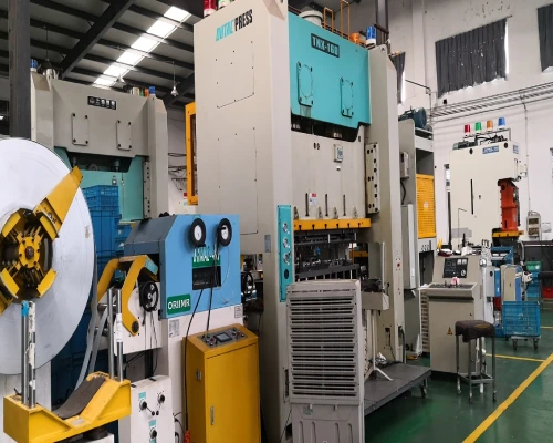
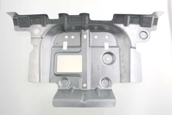
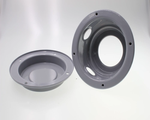
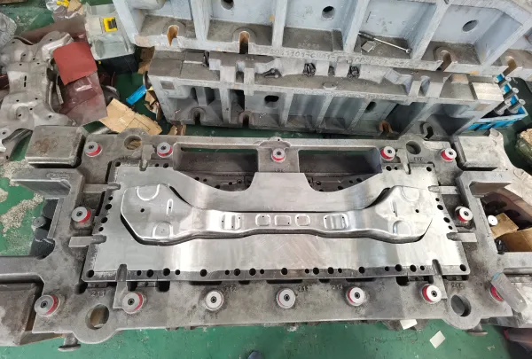
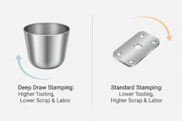
Deep draw stamping is one of the most cost-effective mass production processes in the metal forming industry and is widely used in the automotive, aerospace, home appliance, and general engineering sectors. However, with intensifying global competition and rising raw material costs, deep draw stamping manufacturers are facing unprecedented cost pressures.
In the overall cost structure of deep draw metal stamping, material costs typically account for the largest share—the purchase cost of most steel coil used for deep drawing operations is approximately 20 to 30 cents per pound, while the scrap recovery price is only 2 to 3 cents per pound, and scrap disposal costs often exceed its recovery value. Therefore, maximizing material utilization has the most profound impact on the final product cost and profit margins.
On the shop floor of custom deep draw stamping operations, scrap generation begins at the nesting stage and ends with defect control at every process step—excessive lubrication, improper draw bead layout, and redundant drawing passes. Each seemingly minor process deviation accumulates into significant cost losses during mass production.
This article will take a professional metalworking perspective to systematically elaborate on a systematic approach to reducing deep draw stamping process costs through three key pathways: improving material utilization, optimizing process parameters, and reducing scrap.
Optimizing Material Utilization in Deep Draw Stamping
In deep draw stamping, material utilization is a key lever for cost control. Optimizing blank shape, nesting, and draw bead layout can systematically reduce coil consumption and scrap disposal costs, directly increasing profit per unit.
Precise Design of Blank Dimensions and Shape
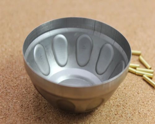
Blank dimensions and shape directly determine material costs and are the primary factor in optimizing material utilization in deep draw metal stamping. The key to blank design lies in using the smallest possible blank while ensuring forming quality; however, blindly reducing blank size may lead to uncontrolled metal flow, causing wrinkling or cracking.
When optimizing blanks, the material’s anisotropic characteristics must be considered simultaneously—the anisotropy value (r-value) directly affects the “earing” phenomenon during the drawing process, and the occurrence of earing results in additional material waste from trimming. Determining the optimal blank contour through finite element simulation can effectively reduce trimming allowances.
Precision blanking methods, such as laser cutting, can control blank dimensional accuracy within ±0.1 mm, reducing material loss by 1%–3% compared to traditional shearing. Precise blank design not only lowers material consumption per unit but also reduces the number of subsequent drawing passes, further reducing the manufacturing costs of deep drawn parts.
Nesting Optimization and Blanking
Nesting optimization is the most direct and fastest-acting technical method for improving material utilization in deep draw stamping. In addition to conventional blank rotation and arrangement methods, the following strategies deserve special attention:
First is multi-part nesting. This involves nesting different parts made of the same material and thickness within the same die, utilizing the scrap areas left after stamping large parts to produce smaller parts. This method not only reduces the total investment in dies but also eliminates the need for an additional press and an extra operator. However, it should be noted that nesting low-volume, deep drawn cup-shaped parts within the scrap area of large, simple stamped parts may slow down the overall production cycle, as the deep draw stamping speed is significantly lower than the blanking and bending speeds.
Second is the lancing process. In progressive dies, lancing is used to create blanks between parts rather than completely punching out the material between them. This method reduces material consumption and shortens the feed pitch. During operation, care must be taken to avoid re-compressing the lanced areas, as this can generate metal slivers and severely impact subsequent custom deep draw stamping processes.
Third is the symmetrical layout of left and right parts. When designing a deep draw stamping die, left and right symmetrical parts should be nested as a single integrated deep drawn blank whenever possible, to be separated in subsequent processes. This method not only significantly reduces material usage but also balances the forces acting on the die.
Through systematic layout optimization, material savings of 3% to 15% can be achieved. In a case study involving a stainless steel stamped part, stainless steel material usage was reduced by 18% through blank optimization and deep drawing simulation.
Material-Saving Effects of Draw Bead Design
A draw bead is used to restrict and control the flow of metal into the die by forcing the material to bend and unbend before entering the die. In draw bead design, the material-saving effects of step beads (also known as offset beads) are particularly notable. Traditional semicircular draw beads must be positioned at a distance from the die cavity—if placed too close, the draw bead area may weaken or even fracture due to excessive thinning. Step beads (also known as offset beads) can be positioned at the opening edge of the binder, closely adjacent to the die cavity without sacrificing strength, thereby effectively reducing blank size.
Furthermore, step beads (Step Bead / Offset Bead) can be set with less force than traditional semicircular draw beads and typically reduce the degree of strain hardening during bending and reverse bending. In applications where a draw bead is not required, the use of a servo-hydraulic cushion can reduce trimming allowances and achieve material savings.
A rational draw bead layout not only ensures forming quality but also reduces blank size without increasing the risk of defects, resulting in significant material savings in deep draw stamping.
Optimization of Deep Draw Stamping Process Parameters
In custom deep draw stamping, process parameter optimization focuses on forming stability and material flow control—streamlining the number of drawing passes, dynamically adjusting the blank holder force (BHF), ensuring precise lubrication, and utilizing simulation-driven processes can significantly reduce the risk of cracking and wrinkling, improve yield rates, and extend die life, thereby systematically reducing unit manufacturing costs.
Rationalization and Streamlining of the deep draw Stamping Process
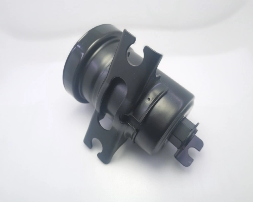
The number of processes in deep draw metal stamping directly determines the scale of die investment and the unit production cost. Each additional drawing operation not only requires extra die stations and stamping equipment but also leads to cumulative work hardening of the material during multiple drawing passes.
By optimizing blank dimensions and shape and adjusting the distribution of drawing ratios across each stage, the number of forming stages can be reduced from four to two. The core constraint in process streamlining lies in the forming limit—reducing the number of stages increases the frequency of tearing, thinning, and cracking, necessitating the use of a Forming Limit Diagram (FLD) to precisely evaluate the safety margins for each stage.
In a case study involving a deep drawn cup-shaped part, by gradually transitioning the draw ratio from 1.8 in the first pass to 1.3 in the final pass, an intermediate annealing step was successfully eliminated while maintaining uniform wall thickness, significantly reducing cycle time and energy consumption.
The number of process steps in custom deep draw stamping directly affects die investment, production cycle time, and unit cost. Reducing the number of drawing passes through process optimization is a key strategy for cost reduction.
Precise Control of Blank Holder Force
Blank holder force (BHF) is the core parameter for regulating material flow rate in the deep draw stamping process. Too low a BHF can cause wrinkling in the flange area, while too high a BHF can lead to sidewall tearing—the process window between the two is often extremely narrow. Traditional constant BHF struggles to adapt to the nonlinear changes in material flow resistance during the drawing stroke. Variable blank holder force (Variable BHF) technology significantly improves forming limits by adjusting BHF in stages throughout the deep draw stamping stroke.
A parameter combination optimized using the Response Surface Method (RSM)—BHF of 13,000 N, stamping speed of 2,000 mm/s, and friction coefficient of 0.14—can limit the maximum thinning ratio of deep drawn parts to within 18.1%. The use of a segmented binder to optimize the spatial distribution of BHF allows for further independent control of material flow into different flange regions.
Lubrication Management in Deep Draw Stamping
In custom deep draw stamping, insufficient lubrication can lead to adhesive wear on the die and surface scratches on parts, while excessive lubrication results in waste, environmental pollution, and increased cleaning costs.
A case study from an OEM manufacturer involving the production of stainless steel steam cups using a three-station deep draw stamping process is particularly instructive: The original process used excessive oil lubrication. After conducting a Fluid Lifecycle Analysis, the manufacturer switched to a precision roller-type lubrication system (Uni-Roller stock lubricator), achieving significant results—a 60% reduction in lubricant consumption and a 30% increase in deep draw die life.
The core principle of lubrication management is “precise application, not excessive application”—replacing traditional spray systems with roller-type lubricators enables uniform application, reduces oil mist and splatter, and improves the working environment.
The Driving Role of Simulation Technology
Finite element analysis (FEA) has become a core tool for optimizing the deep draw stamping process. Prior to die manufacturing, simulation can verify process feasibility, optimize blank geometry, and predict the risk of wall thinning and cracking.
While developing a complex deep draw stamping part, a manufacturer used Stampack simulation to identify a severe thinning risk in a corner. The company immediately consulted with the customer to increase the fillet radius and confirmed the need to add a draw bead to eliminate longitudinal wrinkling—after the redesigned die was installed on the press, compliant parts were produced within just a few stamping cycles. Without simulation support, this process would typically have taken several weeks and required multiple trial runs.
Although investing in simulation technology requires upfront costs, the long-term savings achieved by reducing the number of trial runs, avoiding die rework, and shortening the development cycle far exceed the initial investment. Currently, intelligent optimization methods that combine machine learning and sensitivity analysis are further shortening simulation cycles and improving prediction accuracy.
Only 4 steps
online custom metal fabrication parts
Contact our experts team and experience the efficiency and economic benefits of digital metal fabrication services.
Upload Design Files
STL , STEP (.stp), IGES (.igs), (.ZIP), or PDF.
Also be a sample or an idea
Quote & Design Analysis
Instant factory quotes and DfM reports, the most reasonable solution.
Manufacturing Begins
Digital processes can initiate order tasks within 24 hours.
On-Time Delivery
Keeping delivery promises, approved by 3000+ Global Company buyers.
The Impact of Scrap Reduction and Value Recovery in the deep draw Stamping Process
In deep draw metal stamping, reducing scrap directly impacts the bottom line for material costs—a 1% reduction in the scrap rate translates to significant procurement savings in mass production. Through direct remanufacturing of scrap and die designs optimized to minimize scrap, scrap material can be converted into secondary recycling value, further reducing the total cost per unit.
Reuse of Deep Draw Stamping Scrap
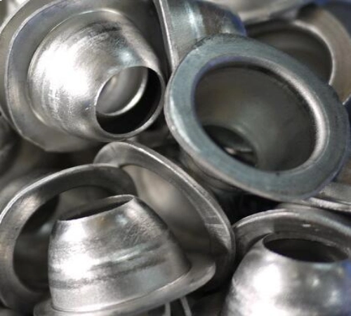
The scrap generated during custom deep draw stamping is not limited to remelting for recycling. Recent studies have shown that aluminum sheet stamping scrap can be directly remanufactured into deep draw stamping parts without going through the remelting process—by cutting blanks from pre-formed stamping scrap and subjecting them to secondary forming, energy consumption associated with aluminum recycling can be significantly reduced.
At the shop floor level, “offal dies” (or “recovery dies”) are a proven and practical method—using scrap generated from the main production process to produce small parts that can be manually fed into line dies or conveyor systems. However, it should be noted that scrap metal may have lost some of its ductility and formability due to prior processing.
The purchase price of coiled material is approximately 20 to 30 cents per pound, while the recycling price for scrap is only 2 to 3 cents per pound; in fact, scrap disposal costs often exceed its recycling value. Therefore, converting scrap into usable parts rather than simply selling it is a more economically viable strategy. In some cases, the scrap rate for deep draw metal stamping can be reduced to less than 2%.
Minimizing Scrap in deep draw Stamping Die Design
Scrap minimization should be incorporated from the die design stage. The dimensions of deep draw blanks must be determined by adding the material to be removed during subsequent trimming to the final part height—this portion is referred to as “engineered scrap.”
A practical rule of thumb is to add an allowance equal to twice the material thickness to account for trimming. By precisely calibrating the die fillet radius and blank holder force (BHF) to control material flow, a more uniform wall thickness distribution can be achieved, thereby significantly reducing the trimming allowance required for stable forming.
In progressive die design, the lancing process forms blanks between parts rather than completely punching out the material, thereby reducing material consumption and shortening the feed pitch. Through systematic die design aimed at minimizing scrap, the scrap rate can be controlled at an extremely low level—a precisely calibrated deep draw stamping process can achieve a scrap rate below 0.8% in high-volume production.
Conclusion
Reducing deep draw stamping costs is a systematic endeavor that requires a coordinated effort across three dimensions: material utilization, process parameter optimization, and scrap reduction. Precise blank design and layout optimization can achieve material savings of 3% to 18%; fine-tuned control of process parameters (BHF optimization, lubrication management, and process streamlining) can lower unit costs while improving quality; the application of simulation technology spans the entire process, preventing waste from the very beginning of the design phase.
For specialized custom deep draw stamping manufacturers, implementing the above strategies not only directly reduces production costs but also enhances market competitiveness by improving process capabilities and quality stability.
Supro MFG is a precision metal fabrication manufacturer headquartered in China and certified to ISO 9001:2015 and IATF 16949:2016. With in-house tooling capabilities, CAE simulation expertise, and a commitment to CPK > 1.33 process control, we provide custom deep draw stamping services and precision stamped parts to global customers in the electronics, automotive, and telecommunications industries.
For technical specifications or inquiries regarding OEM partnerships, please contact our engineering team.