
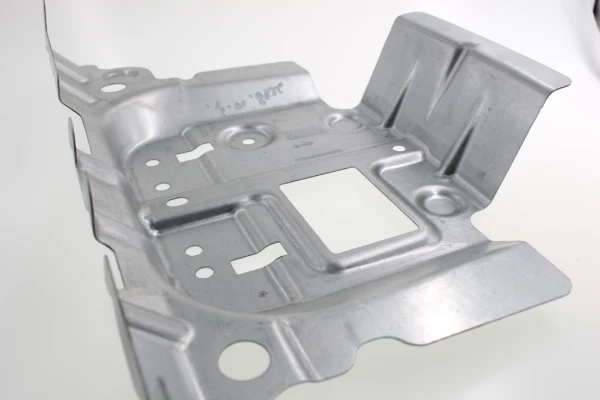

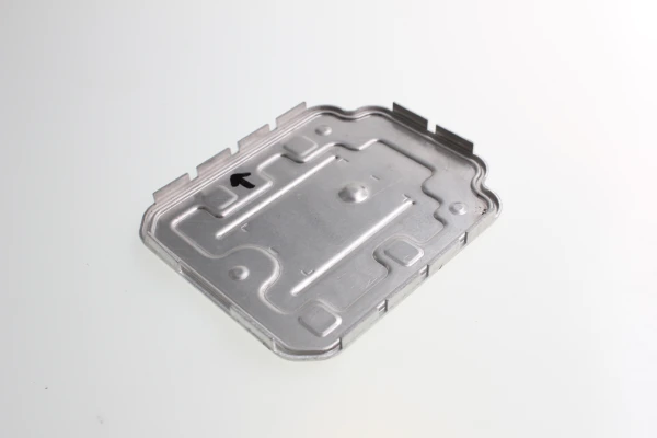
Wall thickness integrity is one of the most critical quality indicators in deep draw stamping. Unlike conventional stamping processes, where the degree of wall thickness thinning is relatively small, the deep draw stamping process subjects the workpiece to complex stress conditions, resulting in uneven wall thickness distribution across the formed geometry. In severe cases, wall thickness reduction at the punch tip can reach 15% to 25% of the original blank thickness, while wall thickness fluctuations along the workpiece surface can affect structural performance, pressure resistance, and dimensional accuracy.
For deep draw stamping manufacturers serving the automotive, aerospace, and pressure vessel industries, understanding the mechanisms of wall thickness reduction and implementing reliable inspection and control strategies are crucial—these are prerequisites for achieving zero-defect production.
This article provides an in-depth analysis of the root causes of wall thickness variations in deep draw metal stamping, reviews current inspection methods, and proposes systematic control strategies based on production practices.
Mechanism of Wall Thickness Reduction in Deep Draw Stamping
In deep draw metal stamping, wall thickness reduction essentially stems from non-uniform plastic flow induced by a combined tensile-compressive stress field. Its distribution is jointly controlled by die radii, friction conditions, and material anisotropy (r-value), and serves as a key criterion for determining forming limits and component structural integrity.
Evolution of the Stress State During Material Flow
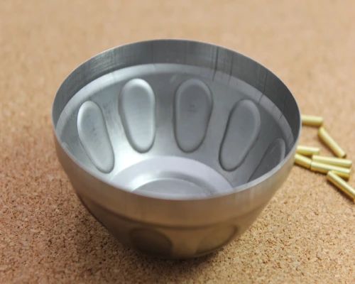
In the deep draw stamping process, the sheet metal flows radially into the die cavity under the action of the blank holder and the die cavity. The flange region is subjected to a composite stress field consisting of radial tensile stress and tangential compressive stress. The forming load is transmitted through the punch radius and the already formed cylinder wall to the deformation zone. When the radial tensile stress exceeds the material’s plastic flow capacity, non-uniform thinning begins to occur along the cylinder wall.
The principle of constant material volume dictates that thinning and thickening occur simultaneously—the outer edge of the flange thickens while the cylinder wall thins. The cylinder wall approaches a plane strain state in the area of contact with the punch; this region experiences the most severe thinning. The maximum thinning rate can reach 15% to 25% of the initial sheet thickness.
Local Thinning at Critical Geometric Features
In deep draw stamping, local thinning is concentrated in the area corresponding to the punch fillet radius. Here, as the punch descends, the material undergoes abrupt bending and reverse bending, causing a sudden change in the strain path. When the punch fillet radius is less than four times the material thickness, tensile stress becomes highly concentrated in the contact zone at the punch nose, significantly impairing the material’s ability to redistribute strain along the cylinder wall.
Increasing the punch fillet radius reduces stress concentration at sharp corners. Simulation results indicate that increasing the punch contour radius from 4 mm to 7 mm effectively reduces the maximum thinning in the cylinder wall, particularly at the corners. Excessive thinning leads to necking and ultimately evolves into fracture—the critical failure state defined in the Forming Limit Diagram (FLD).
Material Anisotropy and Thickness Fluctuations
The plastic strain ratio (r-value) of thin metal sheets directly determines the uniformity of thickness distribution in custom deep draw stamping. Anisotropy causes the sheet material to exhibit differing flow behavior in different rolling directions, resulting in wavy edge defects at the cylinder mouth—known as “earing.” The larger the value of the plane anisotropy index |Δr|, the more pronounced the earing. At the same time, directional fluctuations in the r-value directly translate into thickness fluctuations along the circumference of the cylinder wall.
When the weighted average plastic strain ratio r̄ < 1, the material tends to thin. For critical pressure-bearing deep drawn stamped components, these periodic thickness fluctuations directly affect structural strength and sealing performance, requiring strict control of the r-value and Δr metrics as early as the material procurement stage.
Inspection and Measurement of Thickness Variations in Deep Draw Stamping
In the deep draw stamping process, wall thickness inspection integrates contact gauges, optical scanning, in-line sensing, and simulation-based prediction, upgrading from discrete sampling to full-contour, end-to-end monitoring of thickness distribution.

Contact Measurement Methods
Wall thickness inspection of deep draw stamping parts has long relied on contact gauges—micrometers, calipers, and dial indicators with conical flat probes. These tools are easy to operate and inexpensive, making them suitable for single-point thickness readings in spot-check scenarios. However, variations in the contact force applied by handheld gauges directly affect measurement repeatability; more critically, this method provides only discrete, localized data and fails to reveal the complete thickness distribution of deep draw stamping parts along the cylinder wall and in the circumferential direction.
Higher-precision cross-sectional data can be obtained through wire-cut sectioning followed by observation under an optical microscope; however, this is a destructive testing method and is not suitable for high-volume production scenarios. In the mass production of deep draw metal stamping, contact measurement should be positioned as a supplementary tool for process spot checks.
Non-Contact Optical Scanning
Optical scanning technology has fundamentally transformed the coverage capabilities of thickness inspection in custom deep draw stamping. Structured light scanning systems, such as the GOM Scan 1 and Zeiss ScanPort, generate a complete wall thickness distribution map by performing 3D reconstruction of the part’s inner and outer surfaces and calculating the normal distance. Thickness data obtained by scanning a DP800 duplex steel deep drawn cup using the GOM Scan 1 system showed a high degree of consistency with the numerical simulation results from PamStamp.
Compared to traditional point-based measurement, optical scanning can identify thinning hotspots along the cup wall and circumferential thickness fluctuation patterns. The ARGUS system goes a step further by simultaneously acquiring full-field 3D strain data and precisely locating critical deformation zones. This method is non-destructive and is suitable for die debugging, first-piece inspection, and the deep draw stamping process validation phase.
Process Monitoring Technology
In continuous deep draw stamping production, real-time process monitoring is a critical path to achieving zero-defect quality control. A non-contact ultrasonic thickness gauge is mounted vertically on the outer surface of the deep drawn cup wall and uses oil-immersed coupling to continuously track wall thickness during the forming process—its measurement trajectory is based on the thickness distribution predicted by the process model, enabling real-time detection of thinning changes that lead to tearing.
Eddy current testing combined with multivariate analysis methods has been validated in the quality control of body-in-white parts, demonstrating a significant correlation between eddy current signals and critical thinning levels. Additionally, inductive microsensors based on transformer principles have been developed for quality monitoring in custom deep draw stamping processes. These online sensing technologies enable early warning of thinning anomalies, significantly reducing scrap rates.
Finite Element Simulation for Thinning Prediction
Wall thickness control for deep draw stamping parts is shifting from “post-process inspection” to “pre-process prediction,” with finite element simulation serving as the core tool for this transition. On the AutoForm platform, the “Thinning” parameter is one of the most important criteria for evaluating stamping part quality. By establishing a 3D finite element model—taking into account anisotropic material properties and simplified boundary conditions—it is possible to accurately predict the thickness distribution throughout the entire deep draw metal stamping process.
Parametric analyses using solvers such as ABAQUS/EXPLICIT can quantify the impact of process parameters—such as die fillet radius and blank holder force (BHF)—on wall thickness evolution. The deviation between simulation predictions and measured data from optical scanning can be kept within an acceptable experimental error range. Completing simulation optimization before steel strip cutting enables deep draw stamping manufacturers to identify thinning risk areas in advance and adjust process parameters accordingly.
Only 4 steps
online custom metal fabrication parts
Contact our experts team and experience the efficiency and economic benefits of digital metal fabrication services.
Upload Design Files
STL , STEP (.stp), IGES (.igs), (.ZIP), or PDF.
Also be a sample or an idea
Quote & Design Analysis
Instant factory quotes and DfM reports, the most reasonable solution.
Manufacturing Begins
Digital processes can initiate order tasks within 24 hours.
On-Time Delivery
Keeping delivery promises, approved by 3000+ Global Company buyers.
Methods for Controlling Wall Thickness Uniformity in Deep Draw Stamping
Achieving wall thickness uniformity in custom deep draw stamping is a systematic process—it requires the coordinated interaction of multiple variables, including blank holder force (BHF), die geometry, lubrication, and auxiliary processes, to simultaneously limit the thinning ratio and fluctuation range within acceptable limits.
Optimizing Blank Holder Force (BHF) in the Deep Draw Stamping Process
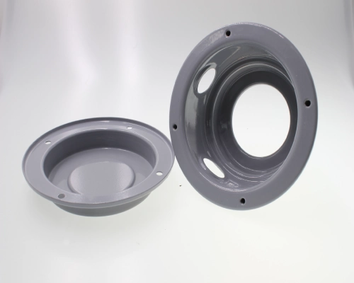
Blank holder force (BHF) is the primary process parameter for regulating wall thickness uniformity in deep draw stamping. Excessively low BHF causes wrinkling in the flange area, while excessively high BHF leads to tearing at the punch fillet. Compared to constant BHF, a variable blank holder force (VBHF) strategy results in a more uniform wall thickness distribution in the deep drawn cup. Optimizing VBHF in segments across the stroke—applying higher pressure early in the forming process to suppress wrinkling and gradually reducing it midway to promote material flow—can reduce the wall thinning ratio from 15.21% to 12.35%.
For complex deep drawn parts, the use of a segmented blank holder in conjunction with spatially variable blankholding force (VBHF) can reduce wall thickness variance by 44% to 70%. The synergistic control of VBHF and variable punch speed has been proven to improve the wall thickness uniformity of deep drawn parts while shortening forming time.
Geometric Design of deep draw Stamping Dies
The die radius directly determines the strain path and thinning distribution in deep draw metal stamping. The die radius (r concave) has the most significant impact on material flow resistance—when r concave is less than 5 times the material thickness, the material undergoes severe bending deformation as it enters the die, and the thinning ratio in the bottom transition zone can exceed 20%; when r concave increases to 8 times the material thickness, the thinning rate can drop to 8%. The concave die radius is typically set within the range of 5–15 times the material thickness.
The punch radius (r convex) primarily affects stress concentration at the transition zone between the bottom and the cylinder wall—when r convex is less than 3 times the material thickness, radial tensile stress rises sharply, and the crack occurrence rate can reach 30%; but when increased to 5 times the material thickness, the crack rate drops below 5%. The punch fillet radius is generally set at 0.7–0.8 times the die fillet radius, and the ratio between the two should be controlled between 0.6 and 0.9.
Ironing as a Secondary Thickness Correction Process
When deep draw stamping alone cannot meet wall thickness tolerance requirements, ironing serves as a downstream correction process to provide final thickness control.
Ironing involves pushing the deep drawn cup through an ironing ring or die with a reduced clearance, causing the material of the cylinder wall to thin uniformly under compressive stress. Design criteria for deep drawn shells typically require that wall thickness reduction not exceed 10% of the initial sheet thickness. In multi-stage deep draw stamping, integrating ironing into each drawing stage can effectively reduce wall thickness reduction and mitigate the tendency for earing. At the same time, the ironing process can also reduce tensile residual stresses in the tube wall, improving the dimensional stability of deep drawn stamping parts.
Lubrication and Parameter Control in the Deep Draw Stamping Process
Lubrication conditions directly influence material flow behavior and wall thickness distribution in custom deep draw stamping by regulating the interfacial coefficient of friction. The flange area experiences the most intense friction, and lubrication conditions in this region directly affect wall thinning and failure. A zoned lubrication strategy—applying varying amounts of lubricant to different areas of the sheet—enables localized control of material flow.
The coefficient of friction is negatively correlated with sheet thickness distribution. Excessive lubrication should be avoided at the contact surface between the punch and the sheet—moderate friction helps promote tensile deformation of the bottom material. In addition, stamping speed, draw ratios, and stress-relief annealing between passes all have significant effects on wall thickness evolution and require systematic optimization for each material grade and deep draw stamping part geometry.
Practical Applications in Deep Draw Stamping Production
In deep draw metal stamping, the engineering value of wall thickness control is ultimately reflected in standardized operations on the production floor—encompassing the establishment of thinning benchmarks, closed-loop control between simulation and measured data, and source control of material properties.
Establishing Thinning Tolerance Benchmarks
In custom deep draw stamping, the starting point for wall thickness control lies in establishing clear thinning tolerance benchmarks for each part. The establishment of these benchmarks requires comprehensive consideration of part functional requirements, material forming limits, and industry standards. For automotive powertrain and pressure vessel components, wall thickness reduction is typically limited to within 10%–15% of the initial sheet thickness; for materials such as 1.4376 stainless steel, it is recommended to limit maximum wall thinning to 18%–20%. Thinning rates exceeding 20%–30% are considered a warning zone, and rates exceeding 30% enter the critical failure zone.
For aluminum alloys and copper materials with excellent formability, the thinning rate per operation can be controlled between 30% and 50%, while for materials with poor ductility, such as high-strength steel, it must be reduced to 20%–30%. Typical dimensional tolerances for deep draw stamping range from ±0.05 mm to ±0.25 mm. Prior to production, these benchmarks must be translated into die design specifications, process parameter windows, and inspection standards to ensure that the entire process—from the first article to mass production—is conducted in accordance with established guidelines.
Integrating Simulation with Deep Draw Stamping Production Feedback
Best practice for wall thickness control in the deep draw stamping process involves establishing a closed-loop feedback mechanism between simulation predictions and actual production data. Using specialized simulation platforms such as AutoForm R8, forming feasibility assessments can be completed prior to die manufacturing to identify risks of cracking, excessive thinning, and wrinkling. Deviations between the thinning distribution results from the simulation and actual measurement data—such as those from GOM optical scanning—can serve as the basis for model calibration.
Actual thinning data from custom deep draw stamping production is fed back into the simulation model to enable iterative adjustments to material model parameters and boundary conditions, thereby gradually improving prediction accuracy. In its application at PSA Peugeot Citroën, AutoForm has established simulation validation standards for thinning variables within a thickness deviation range of ±0.03 mm to -0.25 mm. This closed-loop model—where “simulation guides production, and production validates simulation”—has significantly shortened the deep draw stamping die debugging cycle and reduced trial die costs.
Material Selection and Incoming Inspection
Wall thickness uniformity in deep draw stamping begins with strict control at the material stage. The plastic strain ratio (r-value) is a key indicator for evaluating a material’s deep drawing performance—the higher the r-value (recommended to be above 1.5), the greater the material’s resistance to thinning in the thickness direction; The minimum requirements for conventional deep drawable materials are an r value of at least 1.6, a work-hardening index (n) of at least 0.2, and an elongation of at least 40%. The yield-to-tensile strength ratio (yield strength/tensile strength) should be kept below 0.65.
Incoming material inspection must cover chemical composition, mechanical properties (tensile strength, yield strength, elongation), and surface quality. Supro’s case studies show that when the thickness tolerance of aluminum sheets is optimized from ±0.08 mm to ±0.03 mm, the yield rate for complex deep draw stamping parts can increase from 65% to 94%. Each batch of material must be verified via a Mill Test Report (MTR) and in-house spectral analysis to ensure it meets forming requirements.
Conclusion
Wall thinning and thickness fluctuations in the deep draw stamping process stem from the fundamental mechanical principles of the forming process—the evolution of stress states, geometric constraints, and material anisotropy. To effectively control these phenomena, a multi-level approach is required: predicting thinning patterns through predictive simulation, performing precise parameter optimization (particularly of BHF and die geometry), implementing process monitoring to detect deviations in real time, and taking corrective actions (such as ironing) when necessary.
For deep draw stamping manufacturers committed to delivering parts with excellent wall thickness consistency, these inspection and control methods are not only a quality assurance measure but also key to enhancing competitive advantage. At Supro MFG, we integrate advanced simulation technology, sensor-based inspection, and rigorous process control to ensure that every deep drawn stamped part meets the wall thickness specifications required for your application.
Are you looking for a reliable deep draw stamping partner? Please contact Supro MFG to discuss your project requirements with our engineering team.