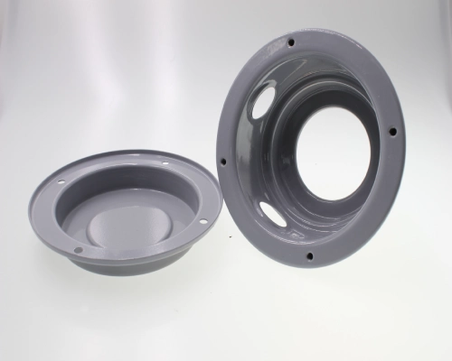
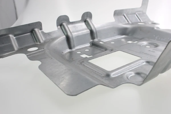
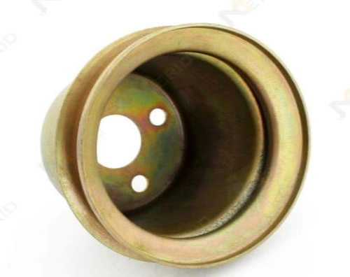
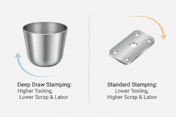
Deep draw stamping transforms flat sheet metal blanks into seamless, hollow parts with complex geometries—where the forming depth exceeds the part’s diameter—in a single stamping cycle. From automotive motor housings to aerospace fuel tanks, deep draw metal stamping delivers unmatched structural integrity and dimensional consistency at production rates of 15 to 40 parts per minute, while eliminating the weak points commonly found in welded assemblies.
However, the cost-effectiveness of custom deep draw stamping is not automatically achieved. Die investment represents the largest upfront capital expenditure, with the cost of a single progressive or transfer die ranging from $10,000 to $50,000. What truly determines a project’s profitability is the control exercised during the design phase over key parameters such as the draw ratio, punch and die geometries, and clearances. The limiting draw ratio (LDR) typically ranges from 1.8 to 2.3; this parameter defines the geometric limits of a single operation—draw ratios exceeding 3.0 require a multi-stage deep draw stamping process supplemented by intermediate annealing.
This article analyzes how core parameters in the deep draw stamping process and die design define the forming window, and explores how to optimize material utilization, extend die life, and reduce trial-and-error iterations while ensuring part quality—ultimately achieving truly cost-effective mass production.
Understanding Deep Draw Stamping Technology
Deep draw stamping transforms flat metal blanks into hollow three-dimensional parts through a single, controlled drawing operation. The punch applies compressive force to the center of the blank, generating tensile and compressive stresses that pull the material radially inward and downward into the die cavity. A blank holder exerts a controlled clamping force to prevent wrinkling.
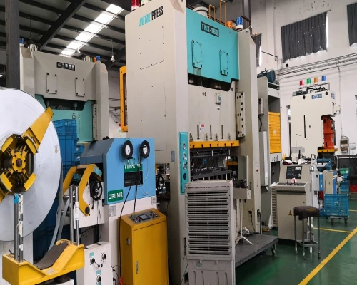
The deep draw stamping process is characterized by a production rate of 15 to 40 parts per minute on a mechanical press, supporting high-volume production and ensuring consistent dimensional repeatability. Unlike progressive die stamping, which primarily involves cutting and bending, deep draw metal stamping produces parts with significant depth relative to their cross-sectional diameter by controlling radial and circumferential material flow.
As a cold forming process performed at room temperature, custom deep draw stamping preserves the metal’s grain structure; compared to hot forming, the resulting parts exhibit superior surface quality and tighter dimensional tolerances. Cold work hardening during the drawing process increases tensile strength by 10% to 30%, depending on the material and draw depth.
Key Design Parameters of the Deep Draw Stamping Process
The economic viability of deep draw stamping is determined as early as the die design stage—the draw ratio, punch and die geometry, clearances, and material properties collectively define the process’s forming window, and deviations in any of these parameters directly affect material flow, die life, and part quality.
Draw Ratio and Limiting Draw Ratio
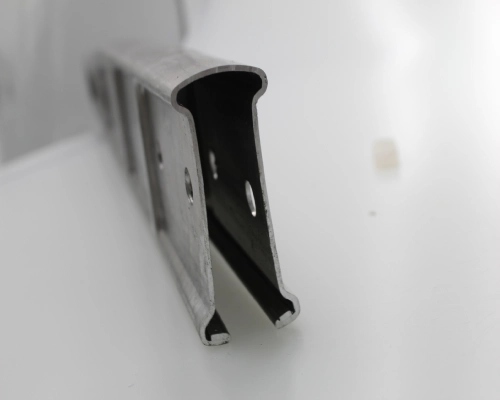
The draw ratio is defined as the ratio of the blank diameter to the punch diameter and is the primary indicator for determining the feasibility of a single deep draw stamping operation. The limiting draw ratio (LDR) is defined as the maximum ratio of the blank diameter to the punch diameter that can be safely drawn without failure. The industry benchmark is that the blank diameter should not exceed twice the punch diameter; the LDR for low-carbon steel typically ranges from 2.1 to 2.3; for aluminum, it is approximately 1.8; and for stainless steel, it can reach 2.0.
An LDR exceeding 2.0 warrants caution, and exceeding 2.4 results in a sharp increase in wall thickness reduction. When the designed draw ratio exceeds the material’s LDR, multi-stage deep draw stamping must be employed, supplemented by intermediate annealing—each time the blank dimensions exceed an LDR threshold, it entails an additional process step, an additional set of tooling, and additional costs.
Punch and Die Geometry
The fillet radii of the punch and die directly control stress distribution and material flow paths. An excessively small die shoulder radius increases drawing force and the risk of tearing; the industry-recommended value is 5 to 10 times the material thickness. For aluminum alloys and stainless steel, a radius of 5 to 10 times the thickness is recommended; studies indicate that wall thickness and stress tend to stabilize at 10 times the thickness.
The punch radius for the first drawing stage is generally 5 to 10 times the material thickness, while the final drawing stage should closely match the part’s bottom radius (deviation ≤ 0.1 mm) . A radius that is too small can lead to stress concentration and material cracking; one that is too large can affect part ejection and dimensional stability.
The clearance between the punch and the die is set between 1.1 and 1.3 times the material thickness; this range provides the optimal balance between allowing space for material flow and avoiding excessive stress. In multi-stage deep draw stamping, the clearance between stages—excluding the final stage—is typically set between 1.1t and 1.5t.
Material Selection and Formability for Deep Draw Stamping
Not all metals are suitable for deep draw stamping. A material’s formability can be quantitatively assessed using two key indicators: the n-value (strain hardening exponent), which describes a material’s ability to resist local thinning during cold deformation; the higher the n-value, the faster the material hardens during drawing and the more uniform the deformation distribution; and the r-value (Lankford coefficient, plastic strain ratio), which measures a material’s resistance to thinning in the thickness direction—the higher the r-value, the better the material’s deep drawing performance.
These two parameters are independent of each other—a high n-value facilitates the forming of complex shapes, while a high r-value directly determines the maximum draw depth achievable in custom deep draw stamping. Low-carbon steel, aluminum, stainless steel, and special alloys each require different combinations of these parameters. Incorrect material selection not only leads to a rise in scrap rates but may also render the entire die design ineffective.
Design for Manufacturability (DFM) in the Deep Draw Stamping Process
Design for Manufacturability (DFM) in deep draw metal stamping does not focus on the part’s appearance—rather, it focuses on how the metal flows, die wear, and how unit costs vary with production volume. If the geometric design fails to fully account for material behavior, it can lead to the need for additional die stations, drive up scrap rates, and tie up press time due to trial-and-error troubleshooting.
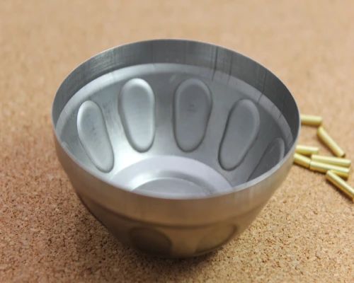
Optimization of Part Geometry for Deep Draw Stamping
Part geometry determines the success or failure of deep draw stamping. The primary principle is to avoid sharp corners—the radius of the punch base fillet should be no less than four times the material thickness; otherwise, stress concentration will lead to localized excessive thinning or even tearing. The recommended radius for the die fillet is five to ten times the material thickness, with forming tending to stabilize at five times the thickness.
Deep draw stamping parts should preferably adopt axially symmetric cylindrical or cup-shaped structures, as asymmetric shapes can cause uneven material flow and tearing. The draft angle should be controlled between 1° and 3° to ensure smooth part ejection, and the ratio of draw depth to diameter must remain within the material’s LDR limit; when this ratio exceeds 3.0, a multi-stage deep draw stamping process is required.
A deeper level of optimization in the deep draw stamping process lies in the blank geometry—a well-designed blank can improve the stress-strain state, increase the maximum draw ratio, and simultaneously reduce the subsequent trimming allowance. If the geometry can be simplified during the design phase without sacrificing functionality, a single die set can save thousands of dollars in manufacturing costs.
Clearance and Material Flow Control
The clearance between the punch and the die acts as the key valve for controlling material flow. If the clearance is too small, the material is excessively squeezed as it passes through, causing the wall thickness to thin sharply and potentially leading to tearing; if the clearance is too large, there is insufficient resistance to material flow, increasing the risk of wrinkling in the flange area.
The industry-standard clearance is set at 1.1 to 1.3 times the material thickness; this range achieves the optimal balance between providing ample flow space and maintaining sufficient restraint. The thickness of the blank holder shims should also be set at 110% of the sheet thickness to accommodate the increase in metal thickness during compression.
In actual deep draw metal stamping production, fine-tuning the clearance often requires a combination of CAE simulation and trial die validation—predicting the material flow path and thinning distribution through finite element analysis, followed by 0.01 mm-level adjustments based on trial stamping results. Correct clearance settings can extend the service life of deep draw stamping dies by more than 30%, while keeping the scrap rate below 2%.
Factors to Consider in Multi-Stage Deep Draw Stamping
When the draw ratio of a single drawing operation exceeds the material’s LDR, a multi-stage deep draw stamping process must be employed. The core of multi-stage design lies in the rational distribution of deformation—each operation bears a portion of the total deformation, ensuring that the draw ratio of any single operation remains below the material’s safety threshold.
Intermediate annealing is an indispensable step in the multi-stage deep draw stamping process—as the number of drawing passes increases, cold work hardening causes the material’s strength to rise by 10% to 30%, while ductility decreases accordingly; annealing eliminates internal stresses and restores the ductility of the grain structure through controlled heat treatment, enabling the material to withstand subsequent drawing without tearing.
Multi-stage design requires balancing die investment, the number of operations, and production efficiency—each additional operation entails extra tooling costs, but it is also the only viable path to achieving the target depth.
Are you looking for reliable & cost-effective
China metal fabrication manufacturer
More than 150,000 OEM metal fabrication products delivered to 5,000+ global buyers.
And benefit from it!
Cost-Effective Deep Draw Stamping Production Strategies
True cost-effectiveness in the deep draw stamping process is not achieved by minimizing initial die investment, but rather by maximizing value throughout the entire production cycle. Material costs typically account for 60% to 70% of a part’s total cost; therefore, material utilization is the single most important lever for cost control. Die maintenance and unplanned downtime are hidden cost drivers that can erode profits in high-volume production. Simulation-based process validation, however, eliminates costly trial-and-error iterations before the actual machining of the die begins.
The following strategies target these three pillars—material, die, and process validation—to achieve quantifiable cost reductions without sacrificing the quality of deep draw stamped parts or production throughput.

Material Utilization in Deep Draw Stamping
Material utilization—defined as the ratio of the finished part’s mass to the blank’s mass—is the primary determinant of unit cost in custom deep draw stamping. The blank’s diameter and height must be precisely calculated based on the final part dimensions using the principle of conservation of volume, while trimming allowances are typically kept within 1–2 millimeters to avoid excessive waste.
For cylindrical deep draw stamped parts, using an offset nesting layout can increase material utilization from 70% to over 85%. Advanced CAD/CAM software can optimize blank positioning to minimize scrap, while precision blanking technologies—such as laser cutting, which achieves accuracy of ±0.1 mm—can reduce initial material loss by 1% to 3% compared to traditional shearing. For high-value alloys, a scrap recycling rate exceeding 90% can further increase overall material utilization by 5% to 10%.
When manufacturing automotive fuel tanks using deep draw stamping technology, scrap can be reduced by 15% to 20% simply by optimizing blank layout. Every one percentage point increase in material yield directly translates into increased profit—which is particularly critical when material costs represent the largest single cost component.
Deep Draw Stamping Die Life and Maintenance
Die life in deep draw metal stamping does not follow a linear trend—the probability of failure follows a “bathtub curve,” characterized by an initial steady-state wear period followed by rapid dimensional drift.
Compared to uncoated tool steel, high-performance coatings such as PVD and CVD can extend blade life by 43 percent—some stamping manufacturers report that CVD TiC coatings enabled 199,000 stamping cycles, compared to only 139,000 for uncoated blades. To maximize the effectiveness of the coating, grinding marks must be polished away before coating; a mirror-like surface finish of Ra 4 or better ensures uniform distribution of shear forces. The cutting edge must be maintained within a very small radius range of 0.001 to 0.002 inches to withstand kinetic energy impacts.
Preventive maintenance of deep draw stamping dies—including daily cleaning and lubrication checks, weekly guide rail inspections, and stroke-count-based component replacements—can reduce unplanned downtime and extend die life. In deep draw stamping production, maintenance costs are always lower than emergency repair costs; by the time burrs become visible to the naked eye, the die clearance has already exceeded the optimal range.
Simulation and Validation
Finite element analysis (FEA) simulation is the most effective tool for eliminating costly trial-and-error processes in the deep draw stamping process. Before cutting any steel, simulation can predict wrinkling areas, tear risks, and wall thinning—a step that can save thousands of dollars in one-time engineering costs.
Modern software such as AutoForm and PAM-STAMP enables engineers to analyze strain distribution, optimize blank holder force (BHF), and validate draw bead geometry entirely within a digital environment. By simulating the forming process, deep draw stamping manufacturers can reduce the number of physical die trials from multiple iterations to just one or two, thereby shortening lead times and saving material that would otherwise be consumed during trial runs.
Providing finite element analysis (FEA) deep draw simulation reports before cutting the die can significantly reduce the risk of costly die rework. The cost of simulation software and the engineering time required represent only a small fraction of the cost of a single die modification—while the benefits will continue to accumulate with each subsequent production run. Simulation technology transforms custom deep draw stamping from an “art” reliant on operator experience into a data-driven “science.”
Conclusion
Cost-effective deep draw stamping cannot be achieved solely through stamping speed or material costs—it requires careful consideration of the draw ratio, die geometry, clearances, and material selection during the design phase. The Limiting Draw Ratio (LDR) defines the geometric boundaries of a single operation; the radii of the punch and die determine material flow and thinning behavior; and clearances determine whether the part can be ejected without issues. These parameters interact with one another, and any errors in custom deep draw stamping production can quickly compound.
Collaborating with an experienced deep draw stamping manufacturer early in the design process—before finalizing the die concept—helps optimize die geometry, material utilization, and process parameters. The result is not only a fully functional part but also a production solution that ensures dimensional consistency, predictable die life, and predictable unit costs throughout the entire production cycle. In the field of deep draw metal stamping, cost-effectiveness is not a byproduct of the production process but rather the result of design.
Supro MFG is a China-based precision deep draw stamping manufacturer certified to ISO 9001:2015 and IATF 16949:2016. With in-house die manufacturing capabilities, CAE simulation expertise, and a commitment to process control with a CPK > 1.33, we provide custom deep draw stamping services and precision stamped parts to global customers in the electronics, automotive, and telecommunications industries. For technical specifications or inquiries regarding OEM partnerships, please contact our engineering team.