
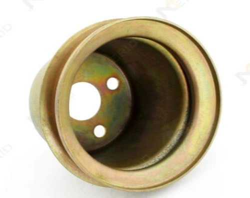
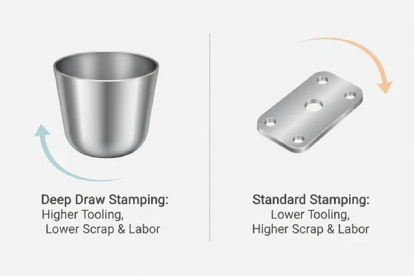

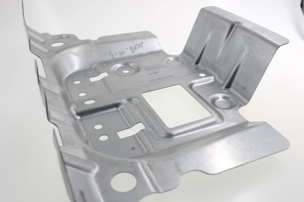

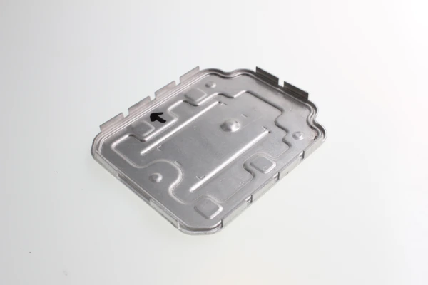
In deep draw stamping, the primary failure modes are wrinkling and tearing—wrinkling is caused by compressive instability, while tearing results from excessive tensile stress and insufficient material flow.
Tearing defects occur when the tensile stress at the radius of the punch tip exceeds the material’s ultimate tensile strength. This defect manifests as localized cracking or complete separation along the drawn wall, typically occurring at the punch tip or along the critical strain zone. It leads to increased scrap rates, prolonged die trial cycles, and compromises the structural integrity of the finished part.
The severity of tearing increases with higher draw ratios, smaller die radii, excessive blank holder force (BHF), and insufficient lubrication. Understanding the mechanical principles of tearing and the process parameters that determine fracture initiation is crucial for developing a reliable deep draw stamping process.
This article explores the root causes of tearing in deep drawn stamped parts, the relationship between process parameters and fracture behavior, and possible corrective measures.
Tear Mechanism in Deep Draw Stamping
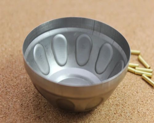
The radius at the tip of the punch represents the critical strain zone where the material undergoes the most severe tensile stress and thinning. Tearing manifests as localized cracking or complete separation along the deep drawn wall—a failure mode in deep draw metal stamping caused by excessive tensile stress and insufficient material flow.
Tensile Stress and Fracture Initiation
Tear defects in deep draw stamping originate at the punch tip radius. As the punch presses down and radially pulls the flattened blank into the die cavity, the material flows along the punch tip radius and is subjected to tensile stress in the radial direction. The punch tip radius represents the critical strain zone—where the material undergoes the most severe tensile deformation.
When draw ratios are too high or the punch radius is too sharp, tensile stress concentrates in the contact zone at the punch tip, thereby reducing the material’s ability to redistribute strain along the drawn wall. A punch radius less than four times the material thickness is a common geometric cause of tearing in deep drawn stamped parts. Once localized tensile stress exceeds the material’s ultimate tensile strength, necking occurs and rapidly progresses to complete fracture.
Local Thinning as a Precursor to Fracture
Thinning refers to the phenomenon of uneven wall thickness distribution on a deep drawn part; it is the primary precursor to fracture in deep draw metal stamping. During the drawing stroke, the material at the punch tip undergoes the most severe tensile deformation, with the amount of thinning at the punch tip typically reaching 15% to 25% of the original blank thickness.
The fundamental characteristics of thinning in the deep draw stamping process are similar to those of necking and fracture in tensile testing—as deformation deepens, the cross-sectional area of the material decreases, while the degree of work hardening increases. When the local strain exceeds the material’s forming limit defined by the Forming Limit Diagram (FLD), the sheet can no longer withstand further deformation and fractures.
Thickness profile plots generated by forming simulation software show the locations of material thinning and areas at risk of tearing. When the minimum thickness change rate reaches approximately 63%, damage occurs and cracks begin to form. Defects in any input parameters—including deep draw stamping die geometry, process parameters, or material properties—can lead to stamping defects even when using deep drawing materials; the limit state manifests as cracks or unacceptable thinning in critical stress areas.
Root Causes of Tearing in Deep Draw Stamping
The root causes of tearing in custom deep draw stamping lie in imbalances in process parameters, defects in die geometry, and limitations in material properties. Excessive blank holder force (BHF) restricts material flow; insufficient die radius causes tensile stress concentration; an excessively high draw ratio exceeds the material’s forming limit; inadequate lubrication increases friction; and unsuitable mechanical properties (low n-value or r-value) hinder the uniform distribution of strain. Each of these factors can independently lead to localized thinning, causing it to exceed the material’s fracture limit.
Excessive Blank Holder Force
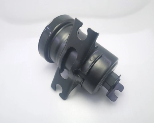
Blank holder force (BHF) is a critical process variable in the deep draw stamping process and must be precisely optimized. Excessive BHF restricts material flow from the flange to the drawing zone; in this case, the wall area is forced to stretch more than expected, leading to increased thinning and causing tearing.
The primary failure modes in deep draw metal stamping are wrinkling and tearing—a low BHF leads to wrinkling, while a high BHF exacerbates tearing. For the deep drawing of square aluminum alloy cups, tearing occurs when the BHF exceeds 18 MPa.
The optimal BHF must be determined for each material-process combination; the goal is to identify a force value that both suppresses wrinkling and maintains sufficiently low flange friction to ensure a stable flow of material throughout the entire stroke.
Insufficient Punch and Die Radii
In the deep draw stamping process, the corner radii of the punch and die directly affect the material’s tendency to tear. When the punch radius is less than four times the material thickness, tensile stress concentrates in the contact zone at the front end of the punch, thereby reducing the material’s ability to redistribute strain along the drawn wall.
An insufficient die entry radius (also less than four times the material thickness) restricts material flow from the flange, causing the tensile load at the front end of the punch to exceed the material’s ultimate tensile strength.
Excessively sharp punch or die radii can cause severe stress concentration; when the sheet metal flows past sharp corners, it is forced into localized stretching, and the strain rapidly exceeds the forming limit, leading to excessive thinning and tearing of the cup bottom. When the geometric parameters of the deep draw stamping die are not optimized, tearing typically occurs at the corners due to concentrated tensile stress.
Excessive Draw Ratio and Blank Size
The draw ratio is the direct relationship between the diameter of the deep draw punch and the size of the blank. Traditional deep draw stamping processes are limited by a certain maximum draw ratio (LDR)—typically 1.8 to 2.3 for low-carbon steel—and exceeding this value will cause the blank to rupture.
If the blank diameter is too large relative to the punch diameter, the resistance to metal flow becomes excessive. Excess material clamped between the die face and the blank holder impedes metal flow, leading to excessive stretching, thinning, or potential cracking. The larger the surface area clamped between the die face and the blank holder, the greater the resistance to metal flow—if the metal cannot flow, stretching occurs; if the stretching is excessive, cracking occurs. As a general rule, the blank diameter should not exceed twice the diameter of the punch.
Insufficient Lubrication in Deep Draw Stamping
Lubrication reduces friction between the blank and the blank holder as well as the die fillets, thereby directly reducing the tensile stress acting on the cup walls. If lubrication is insufficient, friction at the die fillets will impede material flow, forcing the punch to apply greater force to stretch the blank, which significantly increases wall stress and the risk of tearing.
Insufficient lubrication increases the coefficient of friction between the sheet metal and the deep draw stamping die; restricted material flow leads to uneven strain distribution and exacerbates localized over-stretching. When the die surface roughness exceeds Ra 1.6 µm, friction at the interface between the blank and the die increases, thereby raising the load requirements on the punch and accelerating thinning in critical strain areas. Friction plays a crucial role in determining drawability—the limit draw ratio decreases linearly as the coefficient of friction increases.
Material Properties for Deep Draw Stamping
Inappropriate material properties are one of the primary causes of cracking in deep draw metal stamping. The margin for error in many deep draw and stretching processes is inherently very limited; therefore, even the slightest fluctuation in material properties is highly likely to cause cracking. There are two characteristic values that can be used to directly evaluate formability: the n-value (strain hardening index) and the r-value (normal anisotropy).
Materials with a low n-value or high yield strength cannot distribute strain uniformly; localized thinning accelerates, and once the thinning exceeds safe forming limits, cracks will form. A higher r-value indicates greater resistance to thinning and better deep drawing performance.
For custom deep draw stamping applications, it is essential to verify key mechanical properties—including elongation, n-value, r-value, and yield strength. Many successful deep draw metal stamping manufacturers maintain in-house metal testing laboratories to verify material properties before putting the metal into production.
Only 4 steps
online custom metal fabrication parts
Contact our experts team and experience the efficiency and economic benefits of digital metal fabrication services.
Upload Design Files
STL , STEP (.stp), IGES (.igs), (.ZIP), or PDF.
Also be a sample or an idea
Quote & Design Analysis
Instant factory quotes and DfM reports, the most reasonable solution.
Manufacturing Begins
Digital processes can initiate order tasks within 24 hours.
On-Time Delivery
Keeping delivery promises, approved by 3000+ Global Company buyers.
Detection and Diagnosis of Tearing in deep draw Stamping
Detecting tearing early in the custom deep draw stamping process development phase can reduce scrap rates and ensure dimensional conformity of mass-produced parts. Finite element (FE) simulation can predict the occurrence of tearing in a specific deep draw metal stamping operation before the die steel is cut. Forming Limit Diagrams (FLDs) generated by simulation software identify areas where the material is at risk of tearing—FLDs graphically illustrate the forming behavior of sheet metal and show the deformation limits that can be achieved without failure.
In terms of production monitoring, tracking changes in stamping force over time using Statistical Process Control (SPC) can detect process instability before deep drawn stamped parts deviate from specifications. Thickness mapping at critical points—typically using ultrasonic or eddy current sensors—can record wall thickness distribution and identify areas where wall thickness has thinned beyond acceptable limits.
Preventing Tearing in Deep Draw Stamping
To prevent tearing in deep draw metal stamping, systematic interventions are required in areas such as blank holder force (BHF) optimization, die geometry modification, material qualification, lubrication strategies, and multi-stage forming. Each corrective measure addresses the issue of localized thinning—by reducing tensile stress concentration, improving material flow, and distributing strain more uniformly across the drawn wall.
Optimizing Blank Holder Force During Deep Draw Stamping
The most direct measure to address tearing in deep drawn stamped parts is to reduce the blank holder force (BHF), thereby enabling controlled and sufficient material flow from the edges toward the drawn area. However, BHF should be optimized rather than simply minimized—excessively reducing BHF may prevent tearing at the cost of inducing wrinkles.
Variable blankholder force (VBHF) technology applies different force values at different stages of the drawing stroke, effectively eliminating tearing while suppressing wrinkling. The force curve can start at a higher value to suppress initial wrinkling and gradually decrease as the drawing depth increases, allowing the metal to flow smoothly without tearing.
In addition, the pad gap should be set to 105% to 110% of the blank thickness to allow for compression thickening.
Modifications to the Geometry of deep draw Stamping Dies
Adjusting die geometry parameters is the second key measure for preventing tearing in deep draw metal stamping.
If the punch fillet radius is too small (less than 4 times the material thickness), tensile stress will concentrate in the contact area at the punch nose, leading to excessive thinning and tearing;
a die entry radius that is too small (less than 4 times the material thickness) restricts material flow from the flange, increasing the load on the punch. The recommended starting value for the die entry radius is 4 to 6 times the material thickness.
The clearance between the punch and the die should be increased by 7% to 15% based on the nominal material thickness to prevent wall scraping and bottom punch-through.
For deep draw stamping dies, tool steel hardness must be maintained within the range of 58 to 62 HRC, and surface roughness must be controlled below Ra 1.6 µm to reduce friction, extend die life, and maintain the dimensional stability of deep drawn stamped parts.
Material Selection for deep draw Stamping
Selecting materials with higher formability—such as deep draw grade (DDQ) steels—can reduce the risk of tearing. Key material properties must be verified before the deep draw stamping process begins: the r-value is an indicator of resistance to thinning; a higher r-value indicates superior deep drawing performance. The n-value quantifies a material’s ability to distribute strain uniformly during forming.
For formability, minimum values for vertical anisotropy (r-value) and work-hardening index (n-value) are typically specified. It is crucial to verify the properties of the metal before commencing custom deep draw stamping production. Whenever possible, the range of mechanical parameters acceptable for the process should be determined, and materials should be qualified based on mechanical property values rather than generic specifications.
Lubrication Strategies for deep draw Stamping
Lubrication directly reduces the tensile stress acting on the cup wall by lowering the coefficient of friction between the blank and the blank holder and die radius. When lubrication is insufficient, friction at the die radius acts as a brake on material flow; the punch must overcome greater resistance, wall stresses rise significantly, and the risk of tearing during deep draw metal stamping increases sharply.
High-viscosity lubricants (100 to 1,000 cSt) form a strong, resilient oil film at the tool-blank interface, effectively reducing the coefficient of friction and preventing surface scratches on deep drawn stamped parts.
The selection of lubricants must take specific materials into account—the forming of advanced high-strength steels and aluminum alloys requires specially formulated lubricants to cope with high contact pressures and heat generation. For materials prone to seizing, such as stainless steel, specialized deep drawing oils containing extreme-pressure additives should be used.
Multi-Stage Deep Drawing
When a part’s draw ratio exceeds the material’s limit draw ratio (LDR), forming cannot be safely completed in a single stamping operation; multi-stage deep draw stamping must be employed. Multi-stage forming distributes the total deformation across multiple operations, with each subsequent step performing a controlled draw reduction. This method reduces peak stress at any single point, enabling deep geometries that cannot be achieved in a single stamping operation.
Annealing is typically required between stages to restore the material’s ductility. The blank holder force (BHF) must be optimized independently for each stage—excessive force at any stage may cause tearing. Purchasing engineers should request that the deep draw metal stamping manufacturer provide FEA simulation reports for multi-stage forming to verify that the draw reduction rate and thickness distribution for each stage fall within the safe forming window.
Control Strategies for the Deep Draw Stamping Process
To effectively control and prevent tearing during deep draw stamping, a systematic, multi-level approach is required that combines die validation, real-time monitoring, and adaptive parameter adjustment:
- Die validation through trial runs. Conduct Forming Limit Diagram (FLD) analysis and forming simulations early in the design phase to predict thinning distribution and the risk of cracking before the deep draw stamping die is manufactured.
- Real-time monitoring. Implement force monitoring at the punch to detect fluctuations in BHF (Blank Holding Force) and trigger automatic press adjustments when parameters deviate from safe limits.
- In-process thickness measurement. Perform ultrasonic thickness mapping at critical locations to record wall thickness distribution and identify areas where wall thinning exceeds acceptable limits.
- Material certification. Verify mechanical properties—yield strength, tensile strength, elongation, n-value, and r-value—by cross-referencing material certificates and supplementing them with internal testing.
- Statistical Process Control (SPC). Track trends in punch force over time to predict die wear and detect process instability, thereby enabling corrective action before deep drawn stamping parts deviate from specifications.
Conclusion
Tearing in deep draw stamping is a fracture defect caused by excessive tensile stress at the radius of the punch tip, typically resulting from excessive blank holder force (BHF), insufficient die radius, excessive draw ratio, inadequate lubrication, or unsuitable material properties.
Prevention requires a systematic approach: optimizing the BHF rather than minimizing it; increasing punch and die radii to reduce stress concentration; selecting materials with higher r and n values; implementing appropriate lubrication measures; and employing a multi-stage forming process for deep drawn stamped parts. Additionally, finite element analysis (FEA) simulations enable early detection and process validation prior to production.
Supro MFG applies these engineering principles to every custom deep draw stamping project—from material selection to die trial runs to production monitoring—ensuring the delivery of parts that meet dimensional and functional specifications and are free of fracture defects.
For technical specifications, customized metal stamping solutions, or OEM partnership inquiries, please contact Supro immediately. Our professional engineering team is ready to provide you with a tailored application solution.