
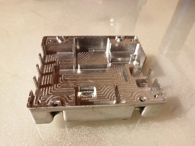

PCB-level EMI/RFI shielding cans are critical components for protecting sensitive electronic circuits from electromagnetic and radio frequency interference. As PCB areas continue to shrink and component density continues to increase, the dimensional accuracy of these stamped enclosures has become a key factor determining SMT assembly yield and overall product reliability.
The core challenge in stamping EMI/RFI shielding cans lies not in the forming process itself, but in managing the physical phenomena that affect geometric accuracy over millions of production cycles. Springback—the elastic recovery of metal after deformation—causes finished part dimensions to deviate from the die geometry. Wear on the edges of progressive dies leads to cumulative drift. Variations in material properties between different coil batches further exacerbate the challenges of process stability.
This article provides an in-depth analysis of the root causes of dimensional deviations beyond tolerance limits during the stamping of EMI/RFI shielding cans and outlines the engineering control measures required to achieve a process capability (CPK) greater than 1.33.
EMI/RFI Shielding Cans Exceeding Dimensional Tolerances: Manifestations and Impact on Assembly
Dimensional deviations in custom EMI/RFI shielding cans—whether in overall length, width, height, or coplanarity—directly affect the yield rate of SMT assembly. Non-coplanar shielding that does not comply with IPC-J-STD-001 requirements can interfere with solder joint formation, while oversized enclosures may encroach on the no-go zones of adjacent components. These geometric defects can lead to placement errors, insufficient solder fill, and reliability risks in the field.
Length, Width, and Height Tolerances of EMI/RFI Shielding Cans
When the length, width, or height of an EMI/RFI shielding can deviates from the nominal dimensions specified in the drawing, it directly affects its physical fit on the PCB. An oversized shielding can intrudes into the keep-out area of adjacent components, causing physical interference that may result in solder joint short circuits or exert mechanical stress on neighboring components; Conversely, shielding cans that are too small cannot establish reliable ground contact with the PCB ground plane, resulting in reduced shielding effectiveness and potentially failing to meet EMC compliance requirements.
For stamped EMI/RFI shielding cans, which typically have a thickness ranging from 0.10 mm to 0.30 mm, typical industry dimensional tolerances are controlled within the range of ±0.05 mm to ±0.10 mm. The cumulative effect of dimensional deviations is particularly significant on densely populated PCBs—where the electrical clearance and creepage distance between adjacent components are already tight—and dimensional deviations in custom EMI/RFI shielding cans may directly violate the electrical spacing requirements specified in IPC-2221.
SMT Placement and Coplanarity Considerations
For automated placement, the most critical dimensional attribute is coplanarity—the flatness of the soldering interface of EMI/RFI shielding cans. Coplanarity is defined as the maximum gap between a component’s contact surface and its mounting plane. Insufficient coplanarity creates unintended gaps between the shielding can and the PCB, making it difficult to form adequate solder joints.
During the reflow soldering process, the surface tension of the molten solder causes the solder to wet the gap between the leads and the pads and form solder joints. If the coplanarity deviation exceeds the range that can be compensated for by the deposited solder paste, some leads will be unable to form acceptable solder joints, resulting in electrical open circuits.
The IPC-A-610 standard requires at least 75% solder fill for Class 3 products. Insufficient solder joints caused by poor coplanarity will directly compromise shielding effectiveness. Furthermore, displacement or tombstoning of the EMI/RFI shield can during the reflow process due to coplanarity issues further reduces SMT assembly yield.
Only 4 steps
online custom metal fabrication parts
Contact our experts team and experience the efficiency and economic benefits of digital metal fabrication services.
Upload Design Files
STL , STEP (.stp), IGES (.igs), (.ZIP), or PDF.
Also be a sample or an idea
Quote & Design Analysis
Instant factory quotes and DfM reports, the most reasonable solution.
Manufacturing Begins
Digital processes can initiate order tasks within 24 hours.
On-Time Delivery
Keeping delivery promises, approved by 3000+ Global Company buyers.
Analysis of the Root Causes of Dimensional Drift in EMI/RFI Shielding Cans
Stamping springback, die edge wear, pitch deviation, and material variations are the primary causes of dimensional drift in custom EMI/RFI shielding cans. These physical and mechanical factors interact during multi-station continuous stamping, leading to a gradual deterioration in geometric accuracy; they must be systematically identified and addressed individually.
Springback
During the unloading phase of the stamping process, the elastic strain energy stored in the bent areas drives angular springback in the walls of the EMI/RFI shielding cans. The extent of this elastic recovery depends on the ratio of the material’s yield strength to its elastic modulus (Y/E ratio); austenitic stainless steel with a high Y/E ratio exhibits more significant geometric deviations. Springback directly manifests as an increase in the outward angle of the side walls and a reduction in overall height, altering the effective enclosure volume of custom EMI/RFI shielding cans.
Accurate compensation requires the introduction of the hardening index (n-value) and the thickness anisotropy coefficient (r-value) to perform nonlinear inverse deformation iterations. If compensation is inadequate, the cumulative angular deviation at a single station can reach 1.5°, which is sufficient to cause the long-edge dimensions to exceed the assembly interface limits.
Edge Wear in Progressive Dies
During the progressive stamping process, microscopic wear on the punch and die edges continuously widens the blanking gap. When the gap deviates from the optimal percentage of the material thickness, the shear band morphology changes, inducing an increase in burrs while causing the blanking contour to shrink.
For the peripheral cutting stations of EMI/RFI shielding cans, edge dullness causes a systematic, unidirectional reduction in the dimensions of the unfolded blank. When uncoated, non-reinforced die steel is used to punch tinned steel strip, the radius of the cutting edge arc increases by approximately 0.005 mm per million punches. This gradual change causes a continuous drift in the length and width dimensions of the finished product in a fixed direction until it exceeds statistical control thresholds.
Inconsistent Feeding Step Length
The step length accuracy of the feeder directly determines the positioning reference of the strip within the die. When the tension of the feeding rollers fluctuates or there is a delay in servo encoder feedback, the actual displacement of the strip deviates from the set step length.
For custom EMI/RFI shielding cans involving deep drawing or multiple bending operations, feeding errors at each station accumulate as a system-wide offset and are superimposed on the final formed features. A feeding deviation of ±0.03 mm is sufficient to cause the sidewall bend line to deviate from the center of the guide pin, resulting in asymmetric forming.
Slippage of the strip caused by insufficient pneumatic clamping force at high stroke rates further exacerbates step distance variability, resulting in parts with differing contours produced by the same die.
Fluctuations in Material Properties of EMI/RFI Shielding Cans
Coils of the same grade but from different batches exhibit measurable inter-batch variations in yield strength and tensile strength, which directly alter the material’s resistance to plastic flow.
During the forming of EMI/RFI shielding cans, an increase in yield strength leads to greater springback; fluctuations in the hardening index (n) affect the uniformity of strain distribution. When fluctuations in the tensile strength of the incoming material exceed ±30 MPa, the amount of warping at the bottom edge of the product varies significantly for the same closing height.
At the same time, differences in anisotropy between the edges and the center of the coil induce asymmetric deformation, resulting in inconsistent diagonal lengths for custom EMI/RFI shielding cans. This factor is often overlooked in process control but is a key source of noise leading to instability in CPK calculations.
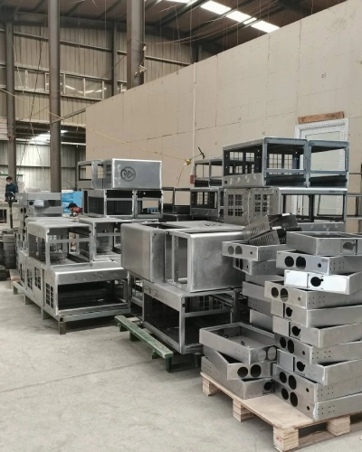
Are you looking for reliable & cost-effective
China Sheet Metal Fabricators
More than 150,000 OEM metal fabrication products delivered to 5,000+ global buyers.
And benefit from it!
Engineering Solutions to Ensure Dimensional Stability
Eliminating dimensional drift in custom EMI/RFI shielding cans requires a systematic engineering approach: the synergistic combination of CAE springback compensation, tungsten carbide anti-wear inserts, and statistical monitoring with a CPK > 1.33 effectively curbs geometric accuracy degradation at its source.
CAE-Based Springback Compensation During the Die Development Phase
During the die development phase for EMI/RFI shielding cans, CAE simulation uses finite element analysis (FEA) to model the complete stamping sequence, predict the magnitude and direction of springback, and generate compensated die surface geometries.
Although this compensation method is simple in principle, its implementation is highly demanding: the simulation first calculates the springback displacement at each node of the formed part, then modifies the die surface geometry by an equal and opposite displacement. This iterative compensation process—which sometimes requires multiple simulation cycles—ultimately generates a die surface that ensures the formed part matches the nominal CAD geometry after springback.
For features such as the sidewall bending of custom EMI/RFI shielding cans, iterative compensation requires incorporating the material’s work hardening index (n-value) and thickness anisotropy coefficient (r-value) to improve prediction accuracy. The engineering value of this method lies in shifting die debugging from a trial-and-error approach to a prediction-based one—completing die surface corrections before the first stamping operation, thereby significantly shortening the trial run cycle and establishing a stable process baseline.
For thin stainless steel sheets with high yield strength, uncompensated dies may produce dimensional deviations exceeding 0.15 mm during the first round of trial production, whereas CAE compensation can control this deviation within ±0.03 mm.
Tungsten Carbide Dies for Improving Dimensional Stability of EMI/RFI Shielding Cans
For high-volume manufacturing of EMI/RFI shielding cans, the choice of materials for the core punch and forming inserts directly determines the sustainable duration of dimensional consistency.
Tungsten carbide (hard alloy) has an HRA hardness of 90 to 93 and a service life 10 to 20 times longer than that of ordinary die steel. It maintains precise positioning accuracy under continuous high-frequency stamping conditions, effectively suppressing progressive dimensional drift caused by cutting edge wear.
At critical stations in progressive dies—particularly those performing blanking, punching, and final forming—tungsten carbide inserts ensure that cutting edge sharpness and forming surface geometry remain stable over millions of stamping cycles. For applications involving the stamping of abrasive materials such as tin-plated steel strip or nickel-silver alloys, the wear resistance of tungsten carbide directly translates into long-term stability of the CPK index, preventing batch-to-batch variations in EMI/RFI shield can dimensions caused by tool changes.

Strict Process Capability Monitoring (CPK > 1.33)
A CPK (Process Capability Index) of 1.33 corresponds to a theoretical defect rate of approximately 64 ppm, which is the basic acceptance threshold for dimensional consistency of stamped parts in the automotive and high-end electronics industries.
From an engineering implementation perspective, a CPK > 1.33 essentially requires that process variation (6σ) not exceed half the width of the tolerance band. To achieve and maintain this capability index for the critical dimensions of custom EMI/RFI shielding cans—length, width, height, and coplanarity—a multi-tiered monitoring system must be established:
Conduct in-line dimensional measurements at defined intervals and track control chart trends;
Deploy real-time tonnage monitoring at each forming station to issue early warnings before out-of-tolerance conditions occur due to tool wear or material variations;
Implement systematic die maintenance scheduling based on punch count and wear trend analysis, rather than relying on reactive interventions after nonconforming EMI/RFI shield cans are detected.
At the same time, an incoming material certification and batch traceability system is used to isolate the impact of raw material performance fluctuations on CPK calculations.
DFM Integration and Multi-Slider Stamping Alternatives
Design for Manufacturability (DFM) analysis identifies potential dimensional risks early in the product development phase—allowing for optimization before the die steel is cut. For custom EMI/RFI shielding cans, DFM reviews focus on design features that exacerbate springback: excessively small bend radii, excessive draw ratios, or asymmetrical geometries. These features can be geometrically optimized to improve formability without sacrificing shielding performance.
In terms of process route selection, multi-slider stamping offers an alternative to traditional progressive dies for specific EMI/RFI shield can geometries. The multi-slide process performs forming operations using multiple slides that move independently in horizontal directions, offering advantages in controlling tolerances for complex bending features.
For the manufacturing of EMI/RFI shielding cans involving multi-directional bending or extremely stringent closing height requirements, multi-slide stamping can complete multiple bending, punching, and trimming operations within a single cycle, thereby reducing cumulative positioning errors between processes.
Looking for a reliable custom sheet metal fabrication companies?
Talk To Supro MFG Expert Team
Contact us for competitive ex-factory prices,
and a full range of technical support services.
Conclusion
Dimensional tolerance overshoot in the stamping of EMI/RFI shielding cans is not an inevitable production problem—but rather a predictable engineering challenge for which proven solutions already exist. Through CAE-based die surface compensation, springback can be predicted and eliminated. The use of tungsten carbide blades can reduce die wear. Strict CPK monitoring allows process drift to be detected and corrected before nonconforming products are produced.
Supro MFG is a China-based manufacturer of precision EMI/RFI shielding cans, certified to ISO 9001:2015 and IATF 16949:2016. With in-house mold manufacturing capabilities, expertise in CAE simulation, and a commitment to process control with a CPK > 1.33, we provide custom EMI/RFI shielding cans and precision stamped parts to global customers in the electronics, automotive, and telecommunications industries.
For inquiries regarding technical specifications, customized project solutions, or OEM partnerships, please contact Supro immediately. Our professional engineering team is ready to provide you with tailored application solutions.