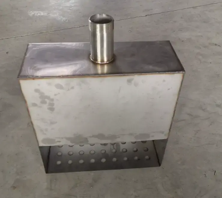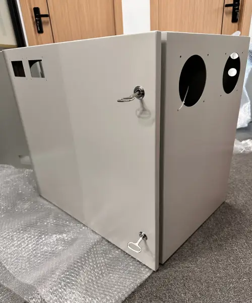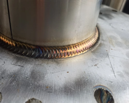
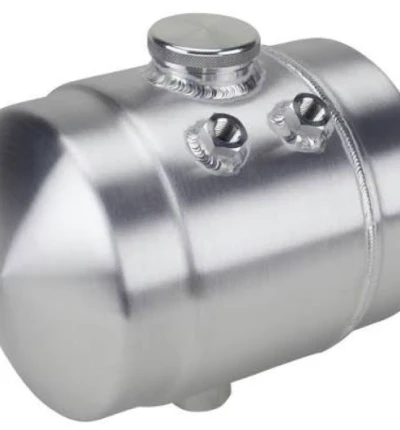


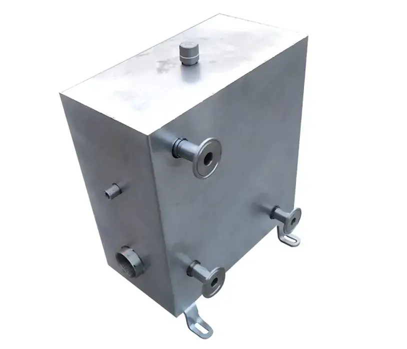


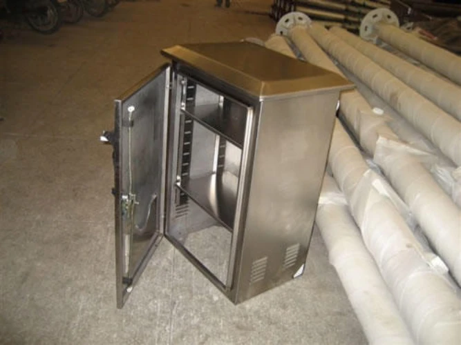
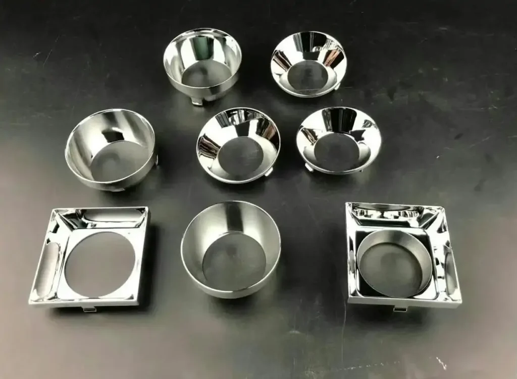
In the manufacturing of metal fuel tanks, internal cleanliness is no longer merely a nice-to-have process metric, but rather a core parameter that determines system reliability.
Modern diesel engine common-rail systems typically operate at pressures exceeding 2,000 bar (200 MPa), with the clearance between precision components inside the injectors ranging from just 1 to 5 micrometers. At this scale, any single particle of metal debris—whether from welding spatter or grinding operations on the metal fuel tank—that enters the common-rail lines with the fuel will cause irreversible abrasive wear to the precision mating surfaces.
Global fuel regulations and leading OEMs recommend that fuel cleanliness meet ISO 4406 18/16/13 standards. However, if welding slag and foreign objects (FOD) remaining from the manufacturing process of custom metal fuel tanks are not thoroughly removed before shipment, the vehicle’s onboard filtration system cannot effectively intercept contaminants already present inside the metal fuel tank.
This means that the manufacturing quality of custom metal fuel tanks directly determines the baseline cleanliness of the fuel system from the very source. Therefore, Supro MFG has established zero tolerance for welding slag spatter and FOD as the bottom line in metal fuel tank manufacturing—from the optimization of welding parameters and endoscopic inspection of blind spots to ultrasonic cleaning and high-pressure air drying, every step in the complete process chain revolves around the engineering commitment to “absolute internal cleanliness.”
This article will systematically elaborate on the systematic control solutions for weld spatter and FOD in metal fuel tank manufacturing from four dimensions: failure mechanisms, process prevention and control, inspection methods, and quality control systems.
Weld Slag and FOD: The Hidden Threat to Metal Fuel Tanks
In metal fuel tank manufacturing, weld slag and foreign objects (FOD) pose a “hidden threat” due to the critical conflict between their physical dimensions and the precise tolerances of fuel systems.
The clearance between internal components in modern high-pressure common-rail injectors typically ranges from 1 to 5 micrometers, whereas the diameter of metal particles generated by welding spatter generally far exceeds this value.When these residues enter the fuel circulation circuit with the fuel, they act as hard abrasive particles, causing irreversible abrasive wear to precision mating surfaces.
If contaminants introduced during the metal fuel tank manufacturing stage are not intercepted at the source, subsequent on-board filtration systems cannot effectively remove particulate matter already present inside the metal fuel tank. Therefore, understanding the sources of welding spatter and FOD, as well as their failure propagation pathways, is the first step in establishing an effective prevention and control system.
Formation and Residuals of Welding Spatter
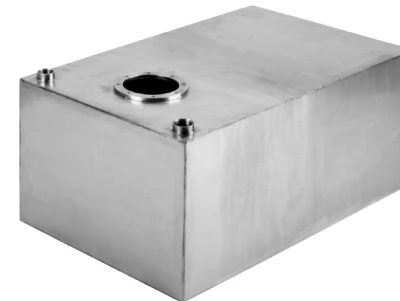
Welding spatter is generated by the spattering of molten metal during the Gas Metal Arc Welding (GMAW) process. When the welding current falls within a specific range during droplet transition, the liquid droplet becomes unstable due to the combined effects of electromagnetic forces and surface tension, causing some molten metal to be ejected before it has fully transitioned into the weld pool.
During the actual welding of metal fuel tanks, a large number of high-temperature metal spatter particles are produced, ranging in size from several hundred micrometers to several millimeters. These spatter particles exist inside custom metal fuel tanks in two forms: loose particles scattered on the tank bottom, or inclusions embedded at the weld seam interface. Regardless of their form, once they are washed into the fuel supply lines by fuel during service, they pose a direct threat to the fuel system.
Sources of Foreign Object Debris (FOD)
In addition to welding spatter, the sources of foreign objects (FOD) inside custom metal fuel tanks span the entire sheet metal manufacturing process.
In the aerospace manufacturing sector, FOD is defined as any foreign object, particle, debris, or medium in the manufacturing environment that may contaminate or damage the product; its categories include raw material scraps, machining debris, tooling and fixture accessories, consumables, and waste.
Specifically in metal fuel tank manufacturing, the primary sources include: metal burrs and chips generated during laser cutting or stamping; abrasive and metal-mixed dust produced during weld bead grinding and surface treatment; chemical residues from auxiliary materials such as anti-spatter agents and cutting fluids; and airborne particles in the workshop environment.
These sources span every process stage, from incoming sheet metal inspection to final assembly. It is worth noting that particulate matter exhibits a bimodal distribution—large particles with diameters greater than 20 micrometers typically originate from welding slag or metal spatter, while extremely small particles of approximately 1 micrometer stem from the condensation of metal vapors—which means that FOD control must address both the macroscopic and microscopic scales simultaneously.
Failure Mechanism: The Path from Residue to Failure
The operating pressure of high-pressure common-rail fuel systems generally exceeds 2,000 bar (29,000 psi). Under these extreme pressure conditions, fuel flows through the precision components inside the injector at extremely high velocities. When welding slag or metal debris from the fuel tank enters the circuit with the fuel, these hard particles cause abrasive wear on the mating surfaces of the valve seat and needle valve.
This wear process manifests as follows: the valve seat sealing surface develops scratches and material spalling due to particle impact, leading to seal failure; the clearance in the needle valve’s guide surface increases due to wear, causing fuel leakage and uncontrolled fuel injection; and the geometry of the nozzle orifice edge changes due to particle erosion, compromising the spray cone angle and atomization quality.
More critically, even if a filter screen is installed at the fuel pump inlet, its design typically allows particles smaller than 100 micrometers to pass through—and the particle size range of welding slag falls precisely within this range.
During service, vehicle vibrations also continuously dislodge slag embedded in the welds, causing the previously clean metal fuel tank to continuously generate new contaminants during use. This means that the lack of FOD control during the metal fuel tank manufacturing phase will translate into field failures months or even years after product delivery.
Only 4 steps
online custom metal fabrication parts
Contact our experts team and experience the efficiency and economic benefits of digital metal fabrication services.
Upload Design Files
STL , STEP (.stp), IGES (.igs), (.ZIP), or PDF.
Also be a sample or an idea
Quote & Design Analysis
Instant factory quotes and DfM reports, the most reasonable solution.
Manufacturing Begins
Digital processes can initiate order tasks within 24 hours.
On-Time Delivery
Keeping delivery promises, approved by 3000+ Global Company buyers.
Source Prevention: FOD Control Strategies in the Welding of Metal Fuel Tanks
When manufacturing metal fuel tanks, the prevention and control of welding slag and FOD should follow the engineering principle that “interception at the source takes precedence over end-of-line cleaning.”
The amount of spatter generated during welding is primarily determined by heat input and the droplet transition mode—when heat input deviates significantly, the spatter rate can surge from a baseline of 1–3% to over 10%. Therefore, minimizing spatter generation during the welding of metal fuel tanks is far more economical and reliable than relying on cleaning methods later to remove adhered weld slag.
We will now outline FOD source control solutions for the welding process from three perspectives: shielding gas composition, selection of anti-spatter agents, and enclosed welding management.
Optimization of Shielding Gas Composition and Welding Parameters
The composition of the shielding gas directly determines the droplet transition mode and spatter rate. Pure argon (100% Ar) enables a smooth droplet transition, with significantly lower spatter than CO₂-containing mixed gases.
For the GMAW process used on carbon steel fuel tanks, an Ar-CO₂ mixture is a common choice—the addition of CO₂ improves penetration and weld bead formation, but an excessively high CO₂ proportion can exacerbate spatter.
Precise matching of welding parameters is equally critical: excessively high voltage causes globular droplet transfer, leading to a sharp increase in spatter rate; a mismatch between wire feed speed and voltage disrupts arc stability. Pulsed GMAW (GMAW-P) can further suppress spatter by precisely controlling peak current and pulse duration. For welding thin sheets of metal fuel tanks, waveform control technology used in short-circuit transfer mode can minimize the spatter rate.
Application Guidelines for Anti-Spatter Agents
Anti-spatter agents form a barrier layer around the weld seam, reducing the adhesion of weld slag to the base metal surface and making spatter easier to remove after welding. An ideal anti-spatter agent should meet the following engineering requirements: water-based formulation, non-toxic, easy to remove, does not contaminate the weld seam, and does not affect downstream painting or electrophoresis processes. During application, a thin, uniform coating must be formed on the surface to be welded. Spray from a distance of approximately 30 cm, and allow the coating to dry for about 10 seconds after application.
In metal fuel tank manufacturing, special attention must be paid to the following: If the anti-spatter agent itself remains inside the tank, it will become a source of chemical Foreign Object Debris (FOD). Therefore, a water-soluble formulation must be selected, and it must be completely removed during the post-welding cleaning process. Nozzle spatter control is equally critical—applying anti-spatter agent to the inner walls of the welding torch nozzle prevents nozzle clogging, which can disrupt the protective gas flow.
Closed-Chamber Management in the Welding of Metal Fuel Tanks
The core logic of closed-chamber management lies in physically preventing spatter from entering the interior of the custom metal fuel tank by providing positive-pressure protection with an inert gas.
Specifically, low-flow nitrogen or argon is continuously introduced into the tank prior to welding to maintain a slight positive pressure inside the tank until no flammable vapors are detected at the outlet. This method has become a standard safety procedure in the repair welding of metal fuel tanks—the container must be thoroughly cleaned and fully inerted before hot work can be performed.
In the mass production of new metal fuel tanks, this principle is extended to the design of welding fixtures: inert gas lines are connected to the fuel tank ports, and gas is continuously supplied during welding to maintain a pressure inside the tank slightly higher than the external atmosphere, thereby blocking the path for spatter particles to enter the tank at the source. The fact that inert gases (such as CO₂ and argon) are heavier than air helps them form a stable protective layer at the bottom of the tank.
Although this process increases gas consumption costs, it is a critical preventive investment for custom metal fuel tanks with high reliability requirements, ensuring zero tolerance for internal FOD.
Are you looking for reliable & cost-effective
China Sheet Metal Fabricators
More than 150,000 OEM metal fabrication products delivered to 5,000+ global buyers.
And benefit from it!
In-Process Inspection of Metal Fuel Tanks: Visual Verification of Internal Blind Spots
After the welding process for custom metal fuel tanks is completed, their enclosed interior cavities create typical blind spots that are not visible to the naked eye. To address this engineering challenge, industrial borescope inspection is the key method for visual verification of internal foreign object debris (FOD). Inspectors insert a miniature camera probe into the interior through existing ports on the tank, scanning the inner walls of the welds and bottom corners section by section to identify weld slag adhesion, grinding dust accumulation, or foreign object residues that are invisible to the naked eye.
Clear acceptance criteria should be established for borescope inspection, including but not limited to:
No free particles visible to the naked eye shall be present on the inner walls of the metal fuel tank;
No adherent spatter shall be present in the weld zones;
No accumulation of dust or debris shall be present on the tank bottom;
All internal surfaces shall exhibit a uniform metallic finish.
For blind spots that cannot be directly observed via endoscopy, indirect control measures should be implemented in conjunction with process assurance measures (such as parameter validation of cleaning processes).
For ferromagnetic metals, such as carbon steel fuel tanks, permanent magnets can be inserted into the tank interior after welding to vibrate and attract loose magnetic weld slag for collection. This method can serve as a pretreatment step prior to endoscopic inspection, reducing the difficulty of subsequent cleaning.
Final Cleaning of Metal Fuel Tanks: Ultrasonic Cleaning and High-Pressure Air Blowing
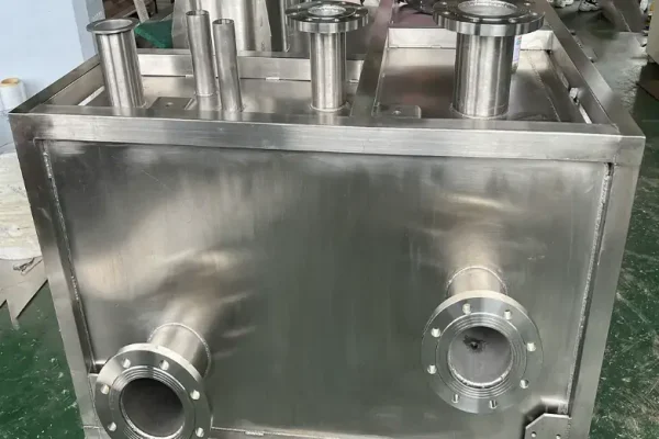
In the metal fuel tank manufacturing process, microscopic contaminants remaining after welding and machining cannot be thoroughly removed by conventional rinsing methods. Ultrasonic cleaning utilizes the cavitation effect generated by high-frequency sound waves in a liquid medium to effectively dislodge welding slag particles and grinding dust adhering to inner walls and blind holes.
Immediately after cleaning, high-pressure drying with precision-filtered clean compressed air must be performed to prevent residual cleaning solution from forming chemical FOD and to avoid the risk of subsequent corrosion caused by trapped moisture.
The ultimate goal of this combined process is to elevate the internal cleanliness of the metal fuel tank to meet acceptance standards in accordance with technical cleanliness specifications such as ISO 16232 or VDA 19.
Principles and Advantages of Ultrasonic Cleaning
The core physical mechanism of ultrasonic cleaning is the cavitation effect. When sound waves generated by an ultrasonic transducer—typically at frequencies between 20 kHz and 40 kHz—are transmitted into the cleaning solution, a large number of micron-sized bubbles form within the liquid. These bubbles rapidly grow and violently collapse during the alternating cycles of acoustic pressure, instantly generating localized high temperatures and high-pressure shock waves. This energy is sufficient to dislodge contaminants such as welding slag particles, grinding dust, and oil residues.
For the complex internal cavity structures and blind spots in weld seams of custom metal fuel tanks, the large cavitation bubbles generated in the low-frequency range (20–40 kHz) are suitable for heavy-duty cleaning tasks; the mid-frequency range (40–80 kHz) strikes a balance between cleaning intensity and surface protection.
Approximately 90% of industrial ultrasonic cleaning applications use a frequency of 40 kHz. The physical cleaning method of ultrasonic waves requires no mechanical contact, thereby avoiding the risk of secondary scratches, and can penetrate microscopic dead corners that traditional rinsing cannot reach, making it the core process for FOD cleaning inside custom metal fuel tanks.
High-Pressure Air Blow-Drying: Eliminating Secondary Contamination
After ultrasonic cleaning is complete, the cleaning solution remaining on the inner walls of the metal fuel tank poses a potential chemical FOD risk. The high-pressure air blow-drying process uses precisely filtered, clean compressed air to forcefully purge the interior of the tank.
The compressed air must be treated by a refrigerated dryer and passed through a 5 μm-grade impurity filter and a 0.3 μm-grade oil mist filter to ensure that the cleanliness of the purging medium meets or exceeds the cleanliness requirements of the parts being cleaned.
The high-speed airflow not only thoroughly expels residual liquid but also carries out any residual particles dislodged during the cleaning process from the tank. For the enclosed cavity structure of metal fuel tanks, the air-blowing direction should follow a path designed from the far end to the near end to avoid driving contaminants deeper into dead-end areas.
Cleanliness Validation for Metal Fuel Tanks: From Qualitative to Quantitative
For custom metal fuel tank projects with high standards, cleanliness validation should be upgraded from qualitative visual inspection to quantitative testing. Currently, the two most commonly used standard systems for cleanliness control in the automotive industry are ISO 16232 and VDA 19.
ISO 16232 defines a standard method for extracting contaminant particles from components: after flushing the inner walls of the metal fuel tank with a liquid, the rinse solution is filtered through a membrane filter, and the particles retained on the filter membrane are then analyzed for size distribution and counted.
VDA 19, on the other hand, combines particle size and count methods with weight-based methods. Specifically for the cleanliness acceptance of metal fuel tanks, specifications typically include upper limits for the number of particles per unit area or per product, particle size distribution thresholds (such as the allowable number of particles in three size ranges: ≥50 μm, ≥100 μm, and ≥200 μm), and upper limits for the total weight of residues.
As a professional metal fuel tank manufacturer, Supro comprehensively records and archives all inspection data to create traceable quality documentation.
Looking for a reliable custom sheet metal fabrication companies?
Talk To Supro MFG Expert Team
Contact us for competitive ex-factory prices,
and a full range of technical support services.
Quality Control System for Metal Fuel Tanks: Standardized Implementation of Zero-Tolerance for FOD
The implementation of zero-tolerance for FOD cannot rely on inspections or cleaning procedures at a single stage; rather, it requires the establishment of a systematic control system covering the entire process from raw material intake to finished product shipment. Metal fuel tank manufacturing involves multiple processes, including blanking, bending, welding, grinding, and cleaning, and each process presents potential risk points for FOD introduction or residue.
Therefore, the core task of the quality control system is to embed FOD control requirements into the operating procedures and inspection standards of each process, ensuring through process design that the zero-tolerance principle is transformed from a concept into executable and verifiable daily operational standards.
Establish a Full-Process FOD Control Map
The essence of an FOD control map is to translate the zero-tolerance requirement into actionable control points for each process step. The AS9146 standard in the aerospace industry explicitly requires organizations to conduct FOD risk assessments based on product characteristics and operational processes to determine zone classifications and control levels.
In the metal fuel tank manufacturing process, the control map must cover all process stages, from sheet metal receipt, laser cutting, bending and forming, welding and assembly, to cleaning and packaging. Each stage should specify the FOD introduction risk level, control measures, responsible personnel, and inspection frequency.
At Supro, our welding stations clearly indicate the monitoring parameters for shielding gas flow and the application specifications for anti-spatter agents; cleaning stations specify the ultrasonic frequency and cleaning time window. These maps are posted in visible locations at each workstation and are dynamically updated as processes change—transforming FOD control from vague management requirements into clear, hands-on operational guidelines for every operator.
Personnel Training and Operating Procedures
Operator awareness and skills constitute the first line of defense in FOD control. Welding operators must undergo specialized training in slag control and master the standard operating procedures for parameter adjustment and the use of anti-spatter agents. Cleaning and inspection personnel must possess professional competence in endoscope interpretation and cleanliness assessment. All operators must understand the engineering rationale behind “zero tolerance for FOD”—not as a dogmatic slogan, but as a substantive commitment to end-user safety and equipment reliability.
Traceability and Documentation
Within the framework of the ISO 9001-2015 quality management system, a comprehensive documentation system for FOD control of custom metal fuel tanks should be established. This includes:
Incoming inspection records for each batch of sheet metal;
Welding process parameters (current, voltage, gas flow rate, welding speed) for each metal fuel tank;
Batch numbers and application records for anti-spatter agents;
Endoscopic inspection imagery and assessment results;
Ultrasonic cleaning process parameters (frequency, temperature, duration, cleaning solution batch number);
Final cleanliness test reports conducted in accordance with ISO 16232 or VDA 19 standards.
All documentation must be archived on a per-unit or per-batch basis to ensure that, in the event of a quality issue with any metal fuel tank shipped from the factory, it can be traced back to every process parameter and inspection record throughout the entire manufacturing process.
Conclusion
Controlling the internal cleanliness of metal fuel tanks is of utmost importance. A zero-tolerance policy for welding slag and FOD should not be limited to a “pass” stamp on inspection reports; rather, it must be integrated into every detail of the process, from design to production.
From optimizing welding parameters and implementing closed-loop management at the source, to in-process endoscopic inspection, ultrasonic cleaning, and high-pressure air drying, all the way to a comprehensive quality control system and traceable documentation covering the entire process—every link in this complete process chain represents the concrete implementation of our engineering commitment to “zero tolerance.”
As fuel systems become increasingly sophisticated, ensuring that every custom metal fuel tank that leaves our factory is absolutely clean and meets the acceptance standards of cleanliness specifications such as ISO 16232 or VDA 19 is our most fundamental quality commitment to every customer. Supro MFG drives every process step with engineering logic and uses verifiable data to uphold the zero-tolerance baseline for quality control.
If you require technical specifications or have inquiries regarding OEM partnerships, please contact our engineering team.