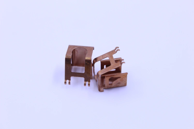




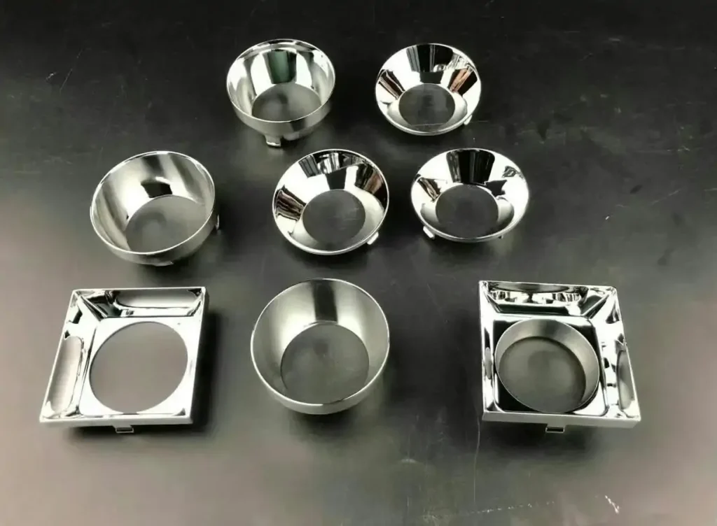
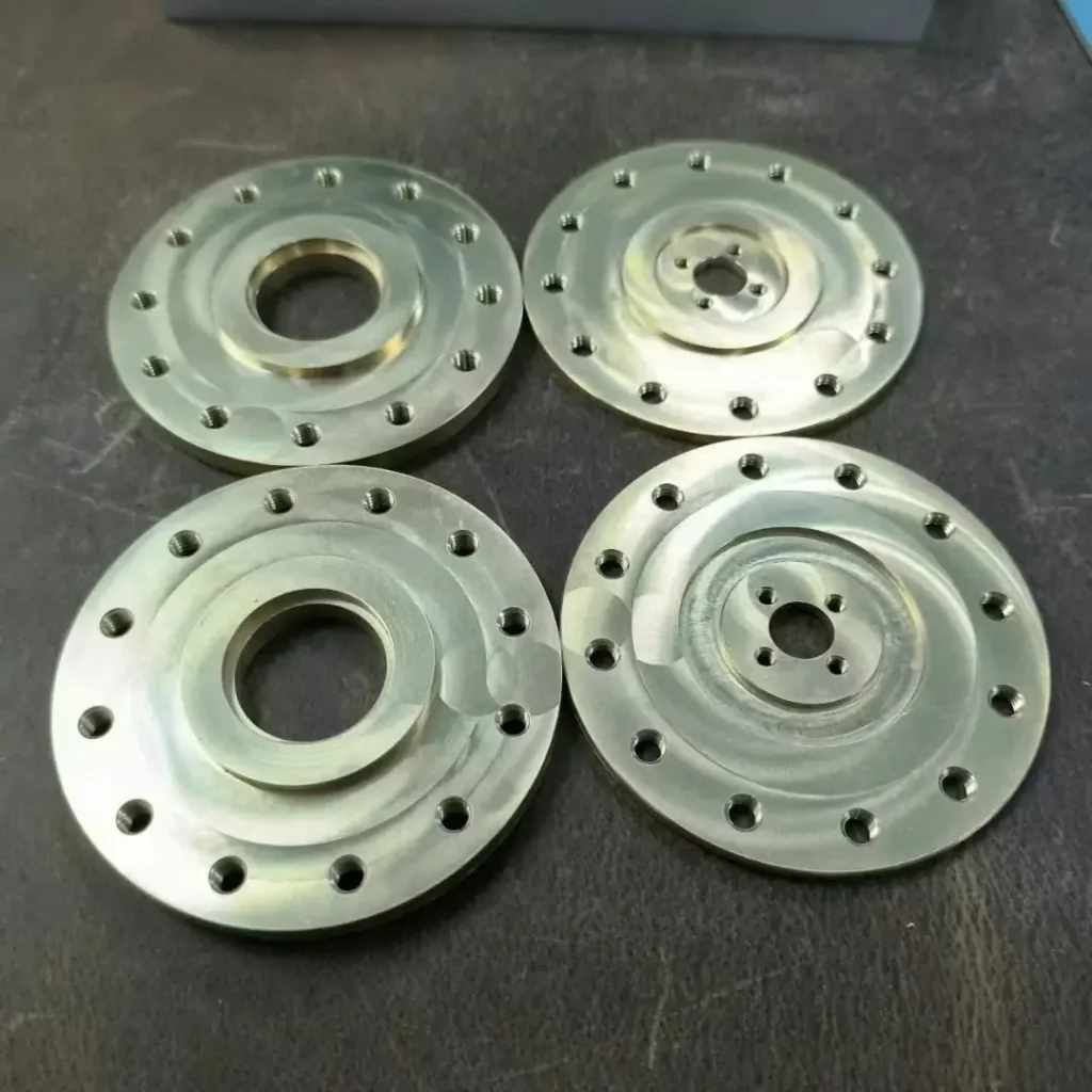
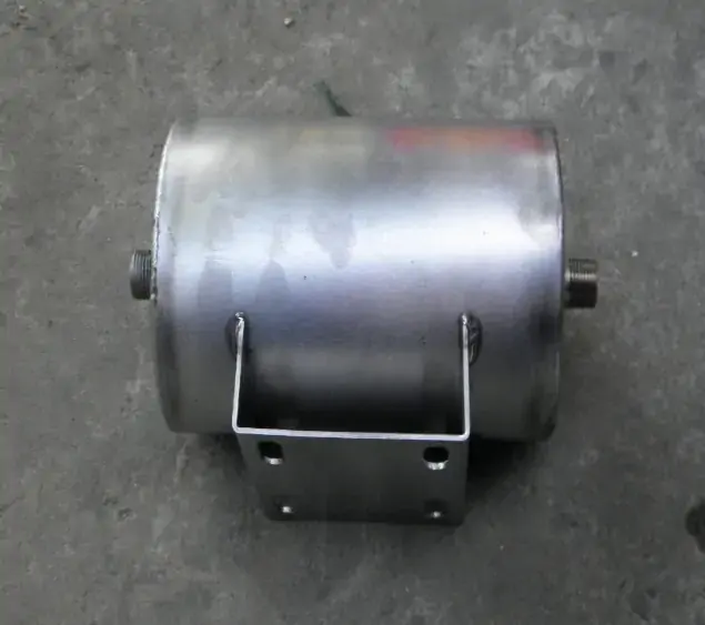
For custom EMI/RFI shielding cans, the plating layer is by no means merely a cosmetic feature—it directly determines the device’s shielding performance and long-term reliability.
When the plating peels off at bent edges or on flat surfaces due to insufficient adhesion, the exposed base material not only triggers galvanic corrosion and accelerates localized oxidation; but fragments of the peeling plating may also contaminate the cleanroom PCBA environment, causing critical functional defects.
The root causes of plating peeling or flaking on EMI/RFI shielding cans typically stem from two factors: First, inadequate degreasing and activation cleaning of the substrate prior to plating, where residual contaminants form a physical barrier between the plating and the substrate; Second, the bending radius is too small, exceeding the ductility limit of the plated metal—when the tensile strain at the bend exceeds the critical value the plating can withstand, microcracks form at the apex of the bend and propagate along the interface under subsequent thermal cycling or mechanical stress.
Whether in mass production of EMI/RFI shielding cans or prototype validation, adhesion should be a controllable, measurable, and verifiable engineering parameter—not a hidden risk.
This article will provide a detailed analysis of the process controls and design considerations necessary to ensure the reliability of plating on custom EMI/RFI shielding cans, including surface pretreatment, bending radius and shielding can geometry design, and quality verification.
Analysis of the Causes of Plating Peeling from EMI/RFI Shielding Cans
The root causes of plating peeling on EMI/RFI shielding cans are primarily due to inadequate surface pretreatment of the substrate and a bending radius design that exceeds the ductility limits of the plated metal.
Substrate Surface Condition—The Foundation of Adhesion
The adhesion of the plating on EMI/RFI shielding cans fundamentally depends on the chemical and physical state of the substrate surface. Residual rolling oil, stamping lubricants, or oxides form a weak interface layer between the plating and the substrate, directly preventing metal bonding.
The ASTM B904 standard explicitly lists adhesion as one of the core process certification requirements for electromagnetic interference shielding coatings—a certification that hinges precisely on thorough and repeatable surface preparation. Alkaline degreasing to remove organic contaminants and acidic activation to strip the native oxide layer and create microscopic roughness are both indispensable. Any deviation in the parameters of either process—such as a drop in temperature, a decrease in concentration, or insufficient dwell time—will directly result in a measurable decline in adhesion.
Bending Radius of EMI/RFI Shielding Cans—The Mechanical Limit of Ductility
Even if the substrate surface is flawless, the geometric design itself can cause plating failure in custom EMI/RFI shielding cans.
Every electroplated metal system has an inherent ductility limit, characterized by the maximum tensile strain the plating can withstand without fracturing. When the bending radius (R) of an EMI/RFI shielding can is less than the material thickness (T), the tensile strain on the outer surface of the bend will exceed the critical ductility limit of most electroplated coatings—particularly nickel or bright tin coatings. This strain induces microcracks at the bend apex; the cracks then propagate along the plating-to-substrate interface and develop into visible delamination during subsequent thermal cycling or mechanical handling.
Specifying a bend radius of R ≥ 1T is a fundamental design criterion for keeping the strain within the elastic range of the plated metal.
Only 4 steps
online custom metal fabrication parts
Contact our experts team and experience the efficiency and economic benefits of digital metal fabrication services.
Upload Design Files
STL , STEP (.stp), IGES (.igs), (.ZIP), or PDF.
Also be a sample or an idea
Quote & Design Analysis
Instant factory quotes and DfM reports, the most reasonable solution.
Manufacturing Begins
Digital processes can initiate order tasks within 24 hours.
On-Time Delivery
Keeping delivery promises, approved by 3000+ Global Company buyers.
Process Control for EMI/RFI Shielding Can Manufacturing—Ensuring Surface Pretreatment Before Electroplating
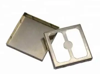
The core of process control for surface pretreatment of EMI/RFI shielding cans lies in the precise calibration of cleaning and activation parameters and the real-time verification of process monitoring methods.
Multi-Stage Cleaning and Activation Procedures
The ASTM B322 standard clearly states that the level of cleanliness required for metal surfaces prior to electroplating far exceeds the requirements of most other coating processes. For the base materials of custom EMI/RFI shielding cans, a single cleaning step is insufficient—the standard cleaning process is divided into three progressive stages: pre-cleaning (using solvents, emulsions, or alkaline sprays to remove major contaminants), intermediate alkaline cleaning, and final electrolytic cleaning.
The alkaline degreasing process is typically conducted at 60–80°C, using appropriate surfactants to saponify and emulsify rolling oils and stamping lubricants. This must be followed by an acid activation stage—typically using a 1%–5% dilute hydrochloric acid or sulfuric acid solution—which not only removes the thin oxide film and fingerprint residues formed during storage or stamping but, more importantly, neutralizes the residual film left by the preceding alkaline cleaning. The activation treatment creates a microscopic roughened surface on the substrate, providing uniform nucleation sites for subsequent electrodeposition.
The process parameters for each stage—temperature, concentration, and dwell time—must be specifically tailored to the substrate material and the type of contaminants.
Process Validation and Solution Maintenance
Setting process parameters is merely a prerequisite; continuous monitoring and maintenance are what ensure the controllability of the pretreatment process for custom EMI/RFI shielding cans.
Saponification byproducts and emulsified oil in the alkaline degreasing bath gradually accumulate as the number of processing batches increases, leading to a decline in degreasing efficiency; meanwhile, rising concentrations of dissolved metal ions in the acidic activation solution impair the activation effect and may cause over-corrosion of the substrate.
As a professional manufacturer of EMI/RFI shielding cans, Supro has established a regular bath analysis system in our production facilities. We monitor the concentrations of active ingredients and impurity levels through titration or instrumental analysis methods, and formulate replenishment or replacement plans based on the analysis results.
Furthermore, process validation should not rely solely on chemical analysis—test coupons made of the same material and in the same condition as production parts should be processed in-line on a regular basis. Surface cleanliness should be rapidly assessed through a water break test, or closed-loop validation should be conducted via subsequent test plating and adhesion testing.
Only by combining chemical monitoring with physical verification can an auditable chain of evidence be established for the stability of the pretreatment process for EMI/RFI shielding cans.
Are you looking for reliable & cost-effective
China Sheet Metal Fabricators
More than 150,000 OEM metal fabrication products delivered to 5,000+ global buyers.
And benefit from it!
Optimizing the Geometry of Custom EMI/RFI Shielding Cans to Ensure Plating Compatibility
The geometric design of EMI/RFI shielding cans directly determines whether the plating will remain intact after forming, and ensuring that the bending radius matches the material properties is the primary constraint.
Bending Radius Specifications for EMI/RFI Shielding Cans—R ≥ 1T Standard
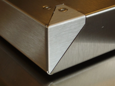
The bending radius of an EMI/RFI shielding can directly determines the strain state of the plating during the forming process. During bending, the outer surface of the material is subjected to tensile stress, while the inner surface is subjected to compressive stress; when the inner bending radius (R) is less than the material thickness (T), the tensile strain on the outer surface will exceed the critical ductility value of most electroplated coatings, inevitably leading to adhesion failure at the bend.
Specifying a bending radius of R ≥ 1T is a fundamental design criterion for keeping the strain on the outer surface within the elastic range of the plated metal. For substrates with low ductility, such as stainless steel (typically recommended at 1.5T–2.5T), or for thicker plating systems, adopting a more conservative radius value is a necessary measure to ensure adhesion integrity.
DFM Collaboration Between Design and Manufacturing of Custom EMI/RFI Shielding Cans
Compliance with EMI/RFI shield can radius requirements must be established during the design phase. When engineers with experience in precision sheet metal manufacturing are involved early on, DFM principles can be embedded into the design before tooling is committed—simplifying geometry, verifying tolerances, and evaluating plating compatibility.
As a specialized manufacturer of EMI/RFI shielding cans, Supro MFG’s DFM process evaluates the geometry of each shielding can based on process capabilities, identifies features that may compromise plating integrity, and recommends design modifications that maintain functionality while ensuring manufacturability.
Treating plating adhesion requirements as manufacturability constraints rather than post-production inspection items helps avoid costly mold rework and the risk of batch scrapping. Effective DFM collaboration transforms bend radii from “design intent” into “shop-floor executable” specifications, ensuring that the plating remains intact after forming.
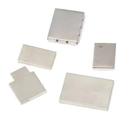
Quality Assurance for EMI/RFI Shielding Cans
The adhesion of the plating on EMI/RFI shielding cans must be quantitatively verified through standardized testing, rather than relying solely on process control based on process parameters.
Cross-Cut Tape Test (ASTM D3359 / ISO 2409)
The cross-cut tape test is the most widely used standardized method for evaluating the adhesion of plating on EMI/RFI shielding cans. ASTM D3359 includes two methods: Method A (cross-hatch) and Method B (multi-blade cross-hatch), while ISO 2409 provides a grading system ranging from 0 to 5.
Procedurally, a specialized grid-cutting tool is used to cut a 1 mm × 1 mm or 2 mm × 2 mm grid pattern into the plated surface, penetrating the plating down to the substrate.
Pressure-sensitive tape is then applied to the grid area and held under constant pressure before being rapidly peeled off at a 180° angle. The rating is determined by the percentage of the coating that has peeled off within the grid area—Grade 0 indicates completely smooth cut edges with no peeling in any square, representing the highest grade. This test is applicable to electroplated parts with a coating thickness not exceeding 50 μm and serves as the standard basis for batch release and process validation.
3M Tape Peel Test for Production Monitoring
The 3M tape peel test is a simplified derivative of the cross-cut method, specifically designed for rapid quality monitoring on EMI/RFI shielding can production lines. Unlike the standard cross-cut method, this test does not involve pre-cutting a grid. Instead, 3M industrial-grade tape—typically from the 3M 600 or 610 series—with a specified peel strength of (10±1) N/25 mm is pressed directly onto the plated surface, particularly in areas of stress concentration such as bent sections or edges, and then rapidly peeled off at a 180° angle.
The operator can immediately determine whether the adhesion meets the standard by visually inspecting the tape’s adhesive side for any transfer of coating particles. Any visible transfer of coating particles triggers an immediate process investigation.
This method is a non-destructive test suitable for 100% in-line sampling, providing real-time feedback on process stability; however, it does not replace the standard cross-cut test as the final basis for batch release.
Supplementary Validation Methods
For high-reliability applications, a single tape test may not be sufficient to comprehensively evaluate the coating adhesion of custom EMI/RFI shielding cans; supplementary validation methods must be introduced.
ASTM B571 specifies a series of qualitative adhesion test procedures, including the bend test (bending the specimen to a specified angle to observe whether the coating cracks or peels off), the impact test (applying an impact load via a falling hammer or pendulum), the file test (advancing a file from the edge of the substrate toward the coating), and the heat-and-quench test (which induces interfacial stress by exploiting the difference in thermal expansion coefficients between the coating and the substrate).
These methods simulate various mechanical and thermal stress conditions that the coating may encounter during assembly, transportation, and service, and can reveal interfacial bonding defects that the cross-cut test may not detect.
For EMI/RFI shielding cans in fields such as aerospace, medical, or automotive electronics, it is recommended to incorporate one or more of these supplemental tests into the quality validation program.
Looking for a reliable custom sheet metal fabrication companies?
Talk To Supro MFG Expert Team
Contact us for competitive ex-factory prices,
and a full range of technical support services.
Conclusion
The adhesion of electroplated coatings on custom EMI/RFI shielding cans is not an abstract quality metric—it is a definable, controllable, and verifiable engineering parameter.
To achieve success, strict adherence to three key areas is essential: removing all contaminants through rigorous surface preparation before plating begins; following design rules that account for the ductility limits of the selected coating system; and confirming adhesion through a validation protocol before parts enter assembly. When these elements are integrated into the EMI/RFI shielding can manufacturing process, plating delamination becomes a preventable defect.
Supro is a specialized manufacturer of custom EMI/RFI shielding cans. Leveraging advanced equipment, extensive manufacturing experience, and a professional engineering team, we provide perfect custom EMI/RFI shielding can solutions to more than 3,000 companies worldwide, along with genuine manufacturer quotes.
For technical consultations, design solutions, or product specifications, please feel free to contact our engineering team at any time.