



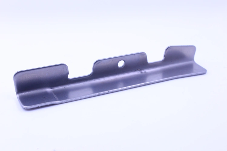
CNC cutting uses a computer program to control how a machine cuts material. CNC stands for computer numerical control. The term covers several processes, from milling a pocket in an aluminum block to laser cutting a flat pattern from sheet steel. The right process depends on the shape of the part, the material and the features that matter most when the part is assembled or used.
Common CNC Cutting Processes
| Process | How it works | When to consider it |
|---|---|---|
| CNC milling | A rotating cutting tool removes material from a secured workpiece. | Parts with pockets, slots, steps, holes or flat mating surfaces, such as an aluminum housing. |
| CNC turning | The workpiece rotates while a tool cuts its outside or inside surfaces. | Parts with features centered on an axis, such as shafts, bushings and threaded fittings. |
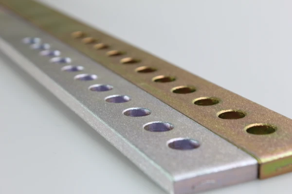
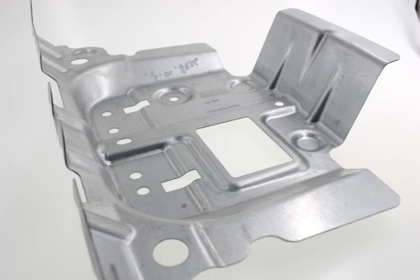
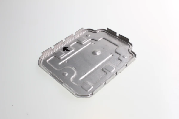
| CNC laser cutting | A focused laser beam cuts a programmed profile, typically from sheet or plate. | Flat metal blanks, brackets or panels with openings that may be bent or assembled later. |
| CNC plasma cutting | A plasma arc cuts electrically conductive materials. | Steel plate blanks where the required edge condition and tolerances suit the process. |
| CNC waterjet cutting | A high-pressure stream of water, often with an abrasive, cuts the material. | Profiles in metal or other compatible materials where avoiding a heat-affected zone is a priority. |
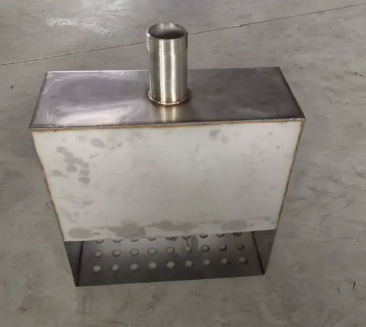
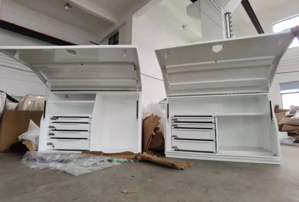
Some parts combine processes. A laser-cut panel can be bent and fitted with threaded hardware. A plate blank can be cut to shape first, then machined where hole position, flatness or surface finish needs closer control.
How the CNC Cutting Process Works
1. Prepare the drawing and toolpath
Start with the part geometry and a drawing that identifies the material, critical dimensions, tolerances and finish. A flat profile may use a DXF file. A part with machined pockets, bores or complex surfaces may need a 3D model and a drawing. Programming then defines the cutting path, cutting sequence and setup for the selected machine.
2. Set up the material and cut the part
Secure the material, set the machine reference and select the tooling or cutting parameters for the material and part geometry. For machined parts, tool access and workholding affect which features can be cut in each setup. For sheet or plate, cutting sequence, nesting and heat input can affect part movement and edge quality.
3. Finish and inspect the part
Check the features called out on the drawing, such as hole position, outside profile, mating surfaces and edge condition. Deburring, threading or finishing may follow, depending on the part. For prototypes or repeat orders, agree which dimensions to inspect and which records are needed before production starts.
Materials and Typical Applications
Metals. Aluminum, carbon steel and stainless steel are common choices. The grade and stock form matter. A thin stainless panel with a flat profile calls for a different setup from a thick aluminum housing with pockets and threaded holes.
Plastics and other materials. Suitable engineering plastics can be milled or turned into fixtures, housings or insulating parts. Other materials may require a different process based on their composition, thickness and response to heat or cutting forces. Confirm compatibility with the chosen process before releasing the job.
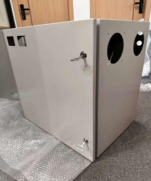
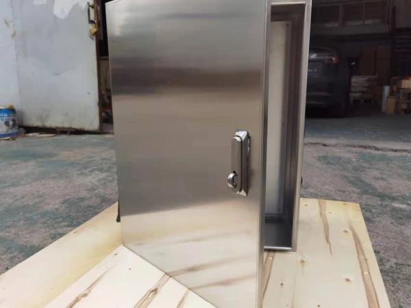
Typical applications include prototype housings, mounting brackets, electronics panels, bushings and machine fixtures. Use the application to identify which features matter. A control panel may need accurate cutout placement, while a shaft may need a controlled diameter and surface finish at a bearing seat.
How to Choose a Process for Your Part
Start with the features on the drawing. A flat sheet profile is a candidate for laser cutting. Deep pockets, threaded holes or precise mating surfaces usually require machining. A round part with concentric features may be suited to turning. For thicker stock, compare the available processes against the required edge condition and whether a second operation will be needed.
When requesting a quote, share the drawing or CAD file, material grade, thickness or stock size, quantity, required finish and the tolerances that affect assembly. Mark which features are critical so the supplier can quote the appropriate cutting, secondary operations and inspection.
For parts with pockets, bores or threaded features, see Supro MFG’s CNC machining services. For flat metal profiles and sheet blanks, see our laser cutting services.