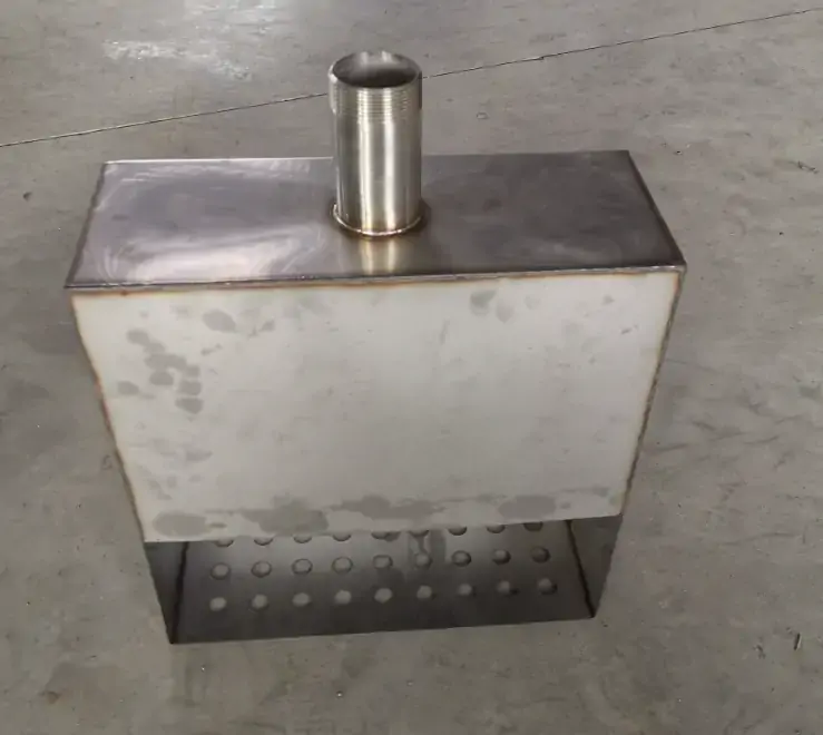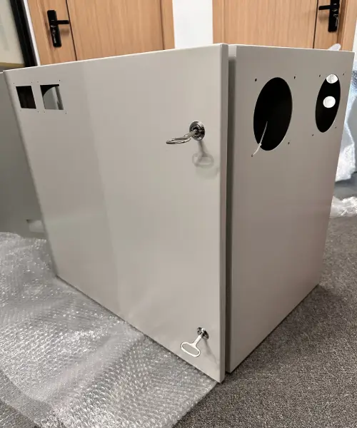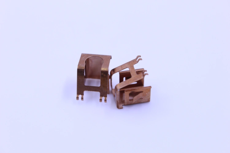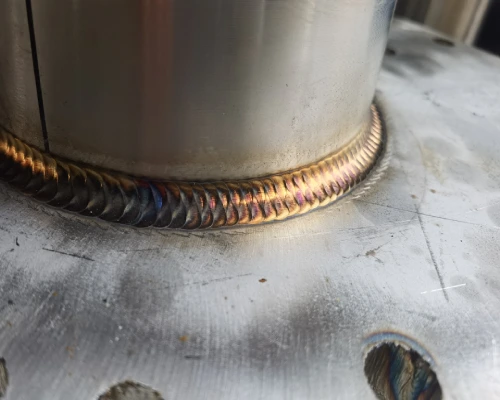
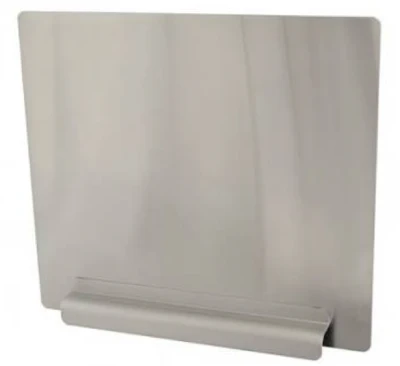




When a splash guard enters final assembly, even the slightest deviation between its mounting holes and the threaded inserts in the equipment frame can cause production line downtime, leading to rework, expedited shipping costs, and delivery delays—which in turn puts pressure on customer relationships.
From a splash guard manufacturing engineering perspective, this misalignment is rarely caused by a single machining error. Rather, it is the result of the accumulation of systemic variables inherent in a multi-stage bending process: tolerance accumulation propagates through successive forming operations, and springback behavior deviates from theoretical predictions when process models fail to adequately account for material properties (yield strength, grain orientation, and thickness variations).
To address these root causes, adjustments at the shop floor level alone are far from sufficient; they require rigorous K-factor calibration through 3D CAD-based development of flat patterns, combined with design-for-manufacturability strategies—such as strategically placing slots to absorb rather than offset assembly tolerances. When these engineering methods are systematically applied, alignment issues with the mounting holes of custom splash guards will transform from a recurring source of on-site failures into a controllable and predictable outcome.
Understanding the Root Causes of Alignment Deviations in Splash Guard Mounting Holes
The root causes of alignment deviations in the mounting holes of custom splash guards lie in the accumulation of tolerances during the continuous bending process and errors in springback prediction—both of which stem from material inconsistencies. The combination of these factors results in a shift in the hole positions relative to the frame.
Accumulation of Tolerances in Multi-Stage Bending Processes
Splash guards typically require multiple bends to form their final protective structure contour, and each bend introduces independent positioning errors and angular deviations. When multiple bends are combined on a single part, these minute deviations accumulate sequentially—a phenomenon known as tolerance accumulation—amplifying what would otherwise be an acceptable single-process error into a significant assembly issue.
Take an angular deviation of ±0.5° in a single bend as an example: after four to five bends, the position of the mounting holes at the end of the part may shift by several millimeters.
Worse still, batch-to-batch variations in material thickness (e.g., the thickness tolerance range for 16-gauge steel is 0.053 to 0.067 inches) and variations in yield strength further exacerbate the uncertainty associated with each bend. For components such as custom splash guards that require precise alignment with threaded holes in equipment frames, the consequences of this cumulative deviation are not revealed until the assembly stage—by which time the cost of rework far exceeds the investment in upfront process control.
Springback Calculation Errors
Springback is a physical phenomenon in which sheet metal partially recovers from deformation after bending, tending to return to its original shape. The springback behavior of different materials—high-strength steel, stainless steel, and aluminum—varies significantly and is influenced by multiple factors, including thickness, grain orientation, and strain hardening index.
When the springback coefficient is calculated inaccurately, the actual bending angle will deviate from the design angle; this deviation is amplified step by step in subsequent processes, ultimately causing the installation holes of the splash guard to deviate from their intended coordinates.
In the air bending process, controlling springback is particularly challenging due to limited contact between the die and the material. Solving this problem cannot rely on empirical estimates; instead, springback parameters must be calibrated for specific material batches through trial bending tests, and the compensation values must be incorporated into the development drawing calculations.
Ignoring the systemic impact of springback means leaving the assembly accuracy of custom splash guards to chance—which is unacceptable in precision sheet metal manufacturing.
Are you looking for reliable & cost-effective
China Sheet Metal Fabricators
More than 150,000 OEM metal fabrication products delivered to 5,000+ global buyers.
And benefit from it!
Precision Engineering Solutions for Achieving Alignment of Splash Guard Hole Positions
To address the issue of misalignment in splash guard mounting holes, the precision solution takes a two-pronged approach: using K-factor-calibrated flat patterns to ensure dimensional accuracy, and employing slotted hole geometries to accommodate assembly deviations.
Calibrating the K-factor Using 3D CAD to Achieve Accurate Flat Pattern Design
The K-factor determines the position of the neutral axis during the bending process—that is, the theoretical plane within the material where neither compression nor elongation occurs. Most CAD software sets the K-factor to 0.44 or 0.50 by default after the material thickness is selected; this historical average is derived from specific operating conditions for air-bending mild steel.
However, when the operator changes the V-die or the material batch varies, the actual inner bend radius changes accordingly, causing the position of the neutral axis to shift.
As a result, the flat pattern generated using the default K-factor is no longer accurate. The correct approach is to conduct test bends for each material grade and thickness—by measuring the bend allowance after bending a sample and calculating the actual K-factor for that specific set of conditions. By entering the calibrated K-factor into 3D CAD for re-unfolding, the dimensional accuracy of each bend in custom splash guards can be ensured from the outset, allowing the positions of mounting holes to be controlled as early as the unfolded drawing stage.
Using Slotted Holes to Accommodate Assembly Tolerances
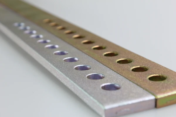
Even with precise K-factor calibration, cumulative tolerances resulting from multiple bends cannot be completely eliminated. Designing some of the splash guard’s mounting holes as elongated, waist-shaped slotted holes is a practical strategy for absorbing tolerances—it allows fasteners to move within the slotted holes in a specific direction, compensating for inevitable manufacturing and installation deviations during the frame assembly phase.
The orientation of the slotted holes should be determined based on a cumulative tolerance analysis: if deviations primarily occur along a specific axis, the slotted holes should extend in that direction. The length of the slotted holes must be quantified and designed based on the expected maximum cumulative deviation, rather than being set arbitrarily. This design does not lower manufacturing precision requirements but provides reasonable tolerance leeway for the on-site installation of custom splash guards, preventing the entire assembly from stalling due to minor hole position deviations.
Only 4 steps
online custom metal fabrication parts
Contact our experts team and experience the efficiency and economic benefits of digital metal fabrication services.
Upload Design Files
STL , STEP (.stp), IGES (.igs), (.ZIP), or PDF.
Also be a sample or an idea
Quote & Design Analysis
Instant factory quotes and DfM reports, the most reasonable solution.
Manufacturing Begins
Digital processes can initiate order tasks within 24 hours.
On-Time Delivery
Keeping delivery promises, approved by 3000+ Global Company buyers.
Design for Manufacturability of Splash Guards: Preventing Misalignment During the CAD Phase
To prevent misalignment of installation holes in custom splash guards during the CAD phase, it is essential to strictly follow reference rules, set feature priorities appropriately, and verify bending allowances for different materials—rather than making passive corrections on the shop floor after forming is complete.
Datum Selection Strategies and Feature References in Splash Guard Design
The strategy for selecting datums in splash guard design directly affects the final positional accuracy of the mounting holes. The ASME Y14.5 standard specifies that the order of datums within a feature control frame determines their priority—the datum on the left has the highest priority, with priority decreasing sequentially to the right. For splash guards with multiple bends, the engineering team should designate the bottom surface as the primary datum and ensure that all mounting hole dimensions are referenced to the same primary datum to avoid tolerance accumulation caused by chain dimensioning.
If the side wall is used as the primary datum, a 0.1° angular deviation over a 10-inch range can result in a 0.017-inch positional offset, equivalent to a 0.034-inch change in the positional tolerance of the diameter.
Incorporating the positioning priority of bend lines relative to hole features into the CAD model is crucial, as the choice of process sequence—bending first followed by punching, or punching first followed by bending—has a fundamental impact on the final hole position accuracy. It is recommended that hole positions be located at least 2.5 times the material thickness plus the bend radius away from the bend line to prevent deformation of the hole features during splash guard fabrication.
Material Selection for Splash Guards and Its Impact on Dimensional Stability
The choice of material for splash guards has a decisive impact on bending accuracy and hole position stability. The springback behavior varies significantly among different material grades—at the same thickness, low-carbon steel exhibits the least springback, followed by 304 stainless steel, while 6061-T6 aluminum alloy exhibits the most significant springback. Material thickness accounts for up to 54% of the impact on springback, while the material type itself accounts for 37%.
High-strength steel exhibits significant springback, stainless steel demonstrates pronounced work hardening, and aluminum has a low modulus of elasticity—the bending characteristics of each material directly affect the final positional accuracy of the mounting holes in custom splash guards. Specifying the material grade and thickness tolerance range in the technical specifications (e.g., a thickness tolerance of 0.053 to 0.067 inches for 16-gauge steel) helps splash guard manufacturers incorporate material properties into their tolerance budget during the process planning stage.
It is recommended to consult with the manufacturer regarding material selection during the design phase of custom splash guards, so that K-factor calibration and springback compensation strategies can be optimized for specific material batches rather than relying on generic parameters.
Looking for a reliable custom sheet metal fabrication companies?
Talk To Supro MFG Expert Team
Contact us for competitive ex-factory prices,
and a full range of technical support services.
Quality Assurance Procedures for Splash Guard Mounting Hole Accuracy
To verify the accuracy of the mounting holes in custom splash guards, first-article inspection must be conducted and validated using a coordinate measuring machine (CMM). Additionally, statistical process control must be implemented throughout the entire production process to ensure that dimensional accuracy remains consistent from pilot production through full-scale mass production.
First Article Inspection and Coordinate Measurement
First Article Inspection (FAI) is a critical step for any batch of splash guards between commissioning approval and production release. Using a coordinate measuring machine (CMM) equipped with a programmable inspection routine, the position of each mounting hole is measured against the nominal values generated from the CAD model. The CMM report records positional deviations along the X, Y, and Z axes, providing complete traceability for each key feature.
For the mounting holes of custom splash guards, positional tolerances are typically controlled within ±0.005 inches in accordance with the ASME Y14.5 GD&T standard. The CMM data is then directly compared against the actual positional tolerances specified in the drawings. Any deviation outside the acceptable range triggers immediate process adjustments before production continues. This verification step ensures that, before any mass-produced parts enter the production line, the hole layout of the splash guard not only conforms to nominal dimensions but also meets the functional design intent.
Monitoring Process Capability Across Production Batches
A single CMM report for the first part alone does not guarantee that subsequent splash guard fabrication will maintain the same dimensional consistency. Statistical Process Control (SPC) addresses this issue by continuously tracking key dimensions—including mounting hole positions, bend angles, and feature spacing—throughout the production process.
Process capability indices (such as Cpk and Cp) are calculated based on sampled measurements. Industry standards require a Cpk value greater than 1.33 for critical features; for the mounting holes of custom splash guards, this means that at least 99.99% of the parts produced by this process fall within tolerance.
Control charts (X̄ charts and R charts) monitor real-time production data against customer specifications. When trends indicate increased variability—such as gradual mold wear or variations in material batches—the system triggers corrective actions before nonconforming splash guard parts are produced.
This closed-loop quality system ensures that the dimensional stability of custom splash guards is reliably maintained from initial sample inspection through full-scale mass production.
Conclusion
Alignment deviations in mounting holes during splash guard fabrication are not an inevitable consequence of sheet metal forming—such issues can be prevented through the systematic application of engineering principles. The root causes—tolerance accumulation during continuous bending and errors in springback prediction—are well-understood variables that can be controlled through K-factor calibration, strategic reference point positioning, and material-specific process parameters.
The use of slotted hole geometry effectively accommodates assembly tolerances without compromising structural integrity. Initial Acceptance Inspection (FAI) verified by a Coordinate Measuring Machine (CMM), combined with Statistical Process Control (SPC) during production, ensures that the dimensional accuracy established during the commissioning phase is maintained throughout the entire large-scale splash guard fabrication process.
Clearly defining these quality specifications—rather than passively responding to on-site failures—reduces project risks, ensures on-time delivery, and eliminates costly rework cycles caused by misalignment of splash guard mounting holes.
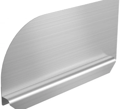
Supro is a professional custom splash guard manufacturer. Leveraging advanced equipment, extensive manufacturing experience, and a dedicated engineering team, we provide perfect custom splash guard solutions to more than 3,000 companies worldwide and offer genuine manufacturer quotes.
For technical specifications, customized project solutions, or business collaboration opportunities, please contact Supro immediately. Our professional engineering team is always ready to provide you with a tailored application solution.