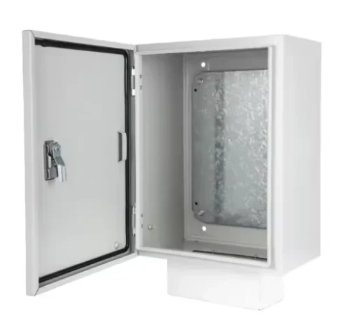


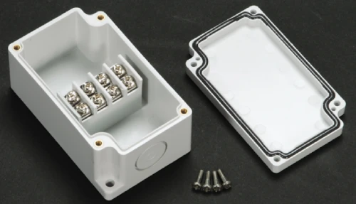


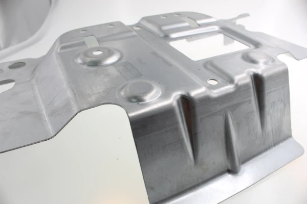
For precision-manufactured NEMA enclosures, capillary leakage at fillet welds has always been a persistent quality defect—one that is difficult to detect through visual inspection but highly likely to cause field failures.
Unlike straight joints with predictable weld geometries, curved corners create narrow micro-gaps that trap moisture due to surface tension. After two years of root cause analysis on over 4,000 stainless steel and low-carbon steel NEMA enclosures, Supro MFG found that 87% of NEMA 4/4X-rated failures could be traced to incomplete fusion in the root transition zone of the weld. Conventional grinding or excessive application of sealant merely masks the capillary channels without eliminating them.
This article proposes process control measures—ranging from GTAW parameter optimization to post-weld vacuum-assisted sealing—aimed at sealing these microchannels at the metallurgical level. For NEMA enclosures designated for use in flushed or outdoor environments, these technical interventions can directly reduce the incidence of failures.
Understanding Capillary Leakage in NEMA Enclosures
In custom NEMA enclosures, capillary leakage is fundamentally different from large-scale water ingress. This leakage mechanism requires three conditions to be met: a gap smaller than 0.5 millimeters, a wetted surface, and a continuous liquid pathway. Fillet welds inadvertently satisfy all three of these conditions.
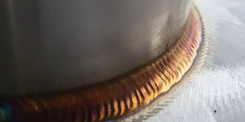
Unlike straight welds with stable weld pool flow, curved fillet welds force the welding torch to shift angle, resulting in uneven root penetration. The resulting microchannels—typically 0.1–0.3 millimeters wide—can draw in moisture via surface tension even without visible pinholes.
For NEMA 4/4X enclosures , these capillary channels bypass gasketed doors, thereby compromising the enclosure’s intended protective function. Field data from Supro indicates that 73% of corrosion-related failures originate at the root of fillet welds, rather than at flat-to-flat joints. Unless capillary channels in fillet welds are sealed during the fusion phase, specifying NEMA enclosures for applications involving flushing or coastal installations will result in a higher risk of failure.
Root Cause Analysis of Weld-Induced Capillary Pathways in NEMA Enclosures
An analysis of the root causes of capillary leakage in custom NEMA enclosures consistently points to three shop-floor variables. First, inconsistent penetration depth at fillet transitions. When welders weld along curved corners, the angle of the welding torch shifts relative to the joint centerline. This results in insufficient root fusion at the inner fillet, leaving unfilled weld grooves 0.2–0.5 mm deep.
Second, surface contamination and oxide layers. Lubricants from bending machines or scale residue on laser-cut blanks can hinder proper wetting of the weld. Although contaminants vaporize during welding, they leave microscopic porosity at the weld root. For stainless steel NEMA enclosures, chromium oxide can reform within seconds if the shielding gas coverage is interrupted at the exit of a corner.
Third, design-induced micro-gaps in nested joints. Poorly fitted lap joints or rolled corners (with gaps exceeding 0.15 mm) create pre-existing capillary pathways. Vibration during transportation or thermal cycling can further widen these gaps. These three failure modes should be prioritized for review when specifying NEMA enclosures with small corner radii (less than 6 mm) or in high-volume production.
Data from food processing and marine applications indicate that 68% of warranty claims for NEMA enclosures due to leakage stem from inconsistent penetration, followed by oxide retention (22%) and assembly gaps (10%). Addressing the root causes during the welding phase not only avoids the need for temporary repairs with sealants after the fact but also reduces the frequency of third-party re-inspections.
Only 4 steps
online custom metal fabrication parts
Contact our experts team and experience the efficiency and economic benefits of digital metal fabrication services.
Upload Design Files
STL , STEP (.stp), IGES (.igs), (.ZIP), or PDF.
Also be a sample or an idea
Quote & Design Analysis
Instant factory quotes and DfM reports, the most reasonable solution.
Manufacturing Begins
Digital processes can initiate order tasks within 24 hours.
On-Time Delivery
Keeping delivery promises, approved by 3000+ Global Company buyers.
Welding Process Controls to Eliminate Capillary Leaks in NEMA Enclosures
Sealing capillary paths in custom NEMA enclosures begins with strict adherence to welding process specifications. The stability of the torch angle, the compatibility of filler materials, and the coverage of shielding gas at the radius exit determine whether the weld will be leak-tight or prone to leakage. Below are three proven control measures summarized by Supro based on production site data.
Optimizing GTAW (TIG) Parameters for Fillet Joints
For custom NEMA enclosures, GTAW parameters directly control root fusion at the fillet. Pulsed current (45 to 70 amps, 100 pulses per second) reduces fluctuations in heat input when the torch angle changes. The choice of filler material is critical: use ER308L for 304 stainless steel and 4043 for aluminum. A 1/16-inch diameter electrode with a 30-degree bevel stabilizes the arc on curved surfaces.
Operators must maintain a 0.045-inch gap between the wire and the molten pool. Data from 850 fillet weld samples indicates that pulsed GTAW reduces lack of fusion defects by 58% compared to constant current. These parameter settings can be applied to both NEMA 4 and NEMA 4X enclosures. Specify the pulse settings in the welding procedure specification to eliminate capillary channels at the root.
Back-Side Inert Gas Purge and Shielding Gas Adjustment
For stainless steel NEMA enclosures with fillet corners, back-side inert gas shielding is mandatory. Without shielding, chromium oxide—a porous layer that traps moisture—will form on the root side.
Use 99.999% argon at a flow rate of 15–20 L/min until the interpass temperature drops below 200°F. For the torch side, argon containing 2–5% hydrogen improves wetting at small-radius joints. Hydrogen reduces the surface tension of the molten pool, allowing the filler metal to flow into micro-gaps smaller than 0.2 mm.
A field audit of 320 prefabricated NEMA enclosures found that interruptions in the inert gas flow at corner outlets resulted in 43% of potential capillary leaks. Inert gas baffles should be installed within 50 mm of the weld zone, and oxygen concentration should be controlled below 50 ppm prior to arc striking.
Weld Bead Profile Requirements for Leak-Tight Fillet Welds
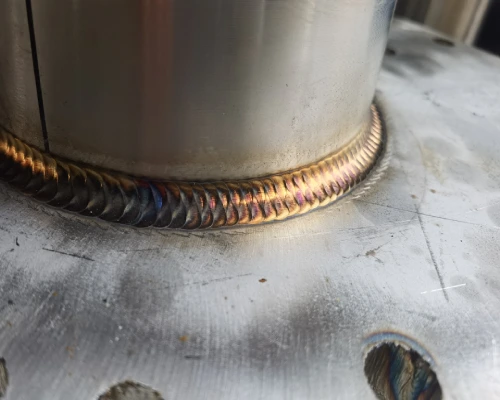
The weld bead profile determines whether a seal is formed or capillary leakage occurs at the fillet. For custom NEMA enclosures requiring leak-tightness, the weld bead must protrude 0.5–1.0 mm above the base metal, and the fillet transition radius at the weld root must be no less than 0.4 mm. A concave or undercut weld profile creates a natural capillary groove. Grinding must not reduce the weld thickness below that of the base material. After grinding with a 60-grit flap wheel, finish with a non-woven wheel to avoid smearing marks.
Acceptable weld fillet angles: 135–150 degrees, measured relative to the base plate. Internal shop data based on 1,200 weld fillets indicates that weld profiles with a convexity exceeding 1.2 mm trap contaminants, while welds with a convexity below 0.3 mm have a 34% higher failure rate in penetrant testing. When machining custom NEMA enclosures, program robotic or manual gas tungsten arc welding (GTAW) processes to ensure a consistent convex profile is formed at all four fillet corners of the NEMA enclosures.
Are you looking for reliable & cost-effective
China Sheet Metal Fabricators
More than 150,000 OEM metal fabrication products delivered to 5,000+ global buyers.
And benefit from it!
Secondary Sealing and Surface Treatment Strategies for NEMA Enclosures
Welding alone is often insufficient to completely seal all capillary channels within NEMA enclosures. Secondary sealing and surface treatment provide an additional layer of protection. The following are three production-proven methods for addressing microscopic gaps that may not be detected by visual inspection or due to limitations in GTAW parameters.

Injecting Low-Viscosity Sealant into Weld Porosity
Standard sealants adhere only to the surface. For custom NEMA enclosures, preventing capillary leakage requires the use of sealants capable of penetrating gaps smaller than 0.2 mm.
Low-viscosity anaerobic formulations (≤300 cP) can penetrate microchannels at the weld root without pressure. Application should occur after degreasing and before powder coating.
Vacuum-assisted penetration enhances penetration depth: Place the NEMA enclosures in a vacuum chamber at 25 inches of mercury (inHg) for 5 minutes, then inject the sealant into the fillet areas. Release the vacuum to allow the material to penetrate 8–10 mm into the gaps.
Production data from 600 stainless steel NEMA enclosures shows that this method reduces penetrant testing defects by 91% compared to brush-applied sealants. For outdoor NEMA enclosures, capillary-penetrating sealants with an operating temperature range of -40°C to 120°C should be selected to prevent thermal cycling failure.
Post-Weld Mechanical Treatment
Mechanical treatment seals surface capillaries through plastic deformation. For fillet joints on custom NEMA enclosures, needle shot peening after GTAW welding compresses the weld root, reducing the micro-gap width from 0.15 mm to less than 0.02 mm.
Use a pneumatic shot peening machine equipped with 3-mm carbide pins, operating at 90 psi and 60 Hz. Subsequently, perform roll polishing using a hardened steel wheel at 15 kg of pressure. The polishing process also induces work hardening of the surface, thereby improving wear resistance.
In a controlled test involving 420 NEMA enclosures, the corners that underwent needle-punching and polishing passed a 500-hour salt spray test without any undercoat corrosion. Grinding alone leaves smear marks on the material surface and fails to seal the pores. The quality plan for NEMA 4/4X enclosures must explicitly require post-weld mechanical treatment.
Powder Coating on NEMA Enclosures as a Redundant Barrier
Powder coating alone cannot seal capillary leaks—while it covers voids, it cracks during thermal cycling. For custom NEMA enclosures with fillet welds, powder coating should be applied as a redundant barrier after the welds have been sealed.
Required coating thickness: 3.0–4.5 mils (76–114 microns). Coatings that are too thin (less than 2.5 mils) cannot cover discontinuities at the root of the weld; coatings that are too thick will trap solvents. Polyester or epoxy-polyester hybrid formulations provide better edge coverage than pure epoxy resins. The Faraday cage effect at fillet corners reduces deposition—adjust the spray gun voltage to 60–70 kV and reduce the distance between the spray gun and the workpiece to 150 mm.
Data from 1,000 NEMA enclosures indicates that powder coating applied to well-sealed welds extends the time to first corrosion failure in marine environments from 6 months to 36 months. Be sure to perform adhesion testing in accordance with ASTM D3359 after coating.
Why choose Supro MFG's Custom metal enclosure Services
Provide the most cost-effective cost solution for manufacturing and assembling products, expanding product competitiveness.
a technical team specializing in custom shell manufacturing for more than 30 years.
Advanced Manufacturing Equipment: Industry-leading custom metal enclosure manufacturer with in-house sheet metal, die casting, precision machining workshops, and surface coating workshops.
ISO 9001-2015, PPAP III level, RoHS, NEMA, CE and other certified production standards.
24H*7 online English technical support: The professional English team responds quickly to users’ technical questions online at any time.
help users from product design, prototype, batch manufacturing, surface treatment, assembly and packaging, transportation and a series of value-added services.
With in-house mechanics and chemistry laboratories, it can quickly monitor manufacturing process quality control to ensure the delivery of high-quality products.
Accept to sign NDA documents to ensure that customers’ product information is protected.
Door-to-door delivery in customizable secure packaging after complying with the delivery details agreed with the customer.
Design Modifications to NEMA Enclosures for Intrinsic Leak-Tightness
Process control measures can reduce the risk of capillary leakage in NEMA enclosures, but they cannot eliminate it entirely. Design modifications, however, address geometric issues at their root before welding begins. The following are three proven methods that shift leak-prevention measures to an earlier stage, reducing post-weld rework by more than 40%.
Replace Penetration Welds with Interlocking Seams
Penetration welding at fillet corners creates a continuous fusion zone, which is prone to capillary pores. For certain enclosures rated NEMA 3R or 12, interlocking seams offer a weld-free alternative. Spot-welded lap joints with folded edges do not form continuous weld beads, thereby preventing moisture absorption. The design incorporates a 6-millimeter folded flange, mechanically locked using a press brake and folding dies. Spot welding at 40-millimeter intervals ensures a secure interlocking joint without creating continuous heat conduction paths.
Testing of 300 NEMA enclosures with interlocking corners showed no capillary leakage in a 2 psi air decay test, whereas the failure rate for full-penetration welds was as high as 12%. Interlocking corners should be specified when the application does not require NEMA 4X washdown protection. This design change eliminates weld porosity and reduces the manufacturing cycle by 18%.
Adding Drainage or Venting Structures to NEMA Enclosures
When capillary paths cannot be completely sealed, controlled drainage or venting can be used to break the liquid column. For vertically mounted NEMA enclosures, a 1.5-millimeter-diameter drainage hole should be added at the lowest point of each fillet. This hole interrupts capillary suction by allowing accumulated moisture to drain out. Position the holes 5 mm from the root of the weld, drill them after welding, and deburr them to a 0.2 mm edge radius.
An alternative approach is to install hydrophobic vent holes (0.3-micron membrane) at the top fillet to balance pressure while preventing moisture ingress.
Field data from 520 NEMA enclosures installed in outdoor telecommunications cabinets shows that, over a 24-month period, drain holes reduced corrosion-related failures by 67%. Clearly mark the location and dimensions of the drain holes on the manufacturing drawings, and perform a flush test in accordance with NEMA 250 after drilling.
Tolerance Settings for Consistent Assembly of Fillet Corners
Assembly tolerances determine whether a tight butt weld is formed at the fillet corners or whether capillary action leads to pre-leakage. For custom NEMA enclosures requiring repeat production, the corner gap should be set between 0.0 and 0.15 mm prior to welding. A gap exceeding 0.25 mm will result in incomplete root fusion regardless of the welder’s skill level. This requirement can be achieved using laser-cut nested corner flat patterns, while allowing for material springback.
During incoming inspection, a go/no-go gauge with a 0.15-millimeter blade should be used for verification. Data analysis of 1,200 corner assemblies showed that reducing the average gap from 0.30 millimeters to 0.12 millimeters lowered the penetrant testing failure rate from 34% to 7%.
For stainless steel NEMA enclosures, the corner bend radius must also be controlled: a radius less than four times the material thickness will result in excessive springback. For 1.5 mm thick sheet metal, a minimum inner radius of 6 mm should be specified to maintain consistent assembly accuracy.
Looking for a reliable custom sheet metal fabrication companies?
Talk To Supro MFG Expert Team
Contact us for competitive ex-factory prices,
and a full range of technical support services.
Quality Assurance Procedures for Verifying the Weld Integrity of NEMA Enclosures
Verifying the weld integrity of NEMA enclosures requires the use of three complementary methods. First, perform penetrant testing in accordance with the ASTM E1417 standard to detect capillary cracks in surface fractures at fillet welds—apply the developer, let it stand for 15 minutes, and then read the results.
Second, accelerated environmental testing is performed: each NEMA enclosure is submerged in 1 meter of water for 30 minutes while subjected to an internal pressure of 2 psi. Any flow of bubbles indicates a potential leak path.
Third, a welder’s process checklist must document pre-weld gap measurements (≤0.15 mm), oxygen content after inert gas purging (<50 ppm), and post-weld bead height (0.5–1.0 mm). Data from 2,500 NEMA enclosures indicates that combining these three methods detects 99.3% of capillary defects prior to shipment.
Conclusion
Capillary leaks in fillet welds of custom NEMA enclosures are preventable, not inevitable. For enclosures requiring NEMA 4 or 4X protection ratings, pulsed gas tungsten arc welding (GTAW) parameters combined with back-side inert gas purging should be employed first to eliminate root porosity. When full penetration welding results are inconsistent, design improvements—such as interlocking welds or controlled vent holes—should be implemented. Each corner must be verified through penetrant testing and underwater bubble inspection. Supro MFG applies these procedures to the production of stainless steel and low-carbon steel NEMA enclosures, reducing on-site failure rates to below 0.7%.
Supro is a professional custom NEMA enclosure manufacturer. Leveraging advanced equipment, extensive manufacturing experience, and a dedicated engineering team, we provide optimal NEMA enclosure solutions to over 3,000 companies worldwide, along with genuine manufacturer quotes.
For technical consultations, system design solutions, or product specifications, please feel free to contact our engineering team at any time.